Hydraulic support element

A support component, hydraulic technology, applied in the direction of engine components, machines/engines, mechanical equipment, etc., can solve the problems of cost quality assurance, and achieve the effect of cost saving

Active Publication Date: 2016-03-23
SCHAEFFLER TECH AG & CO KG
View PDF6 Cites 1 Cited by
  • Summary
  • Abstract
  • Description
  • Claims
  • Application Information

AI Technical Summary

Problems solved by technology

At this point, it is clear to the person skilled in the art that an elaborate quality assurance is additionally required here, which is likewise included in the costs of series production

Method used


Image

  • Hydraulic support element

Examples


Embodiment Construction

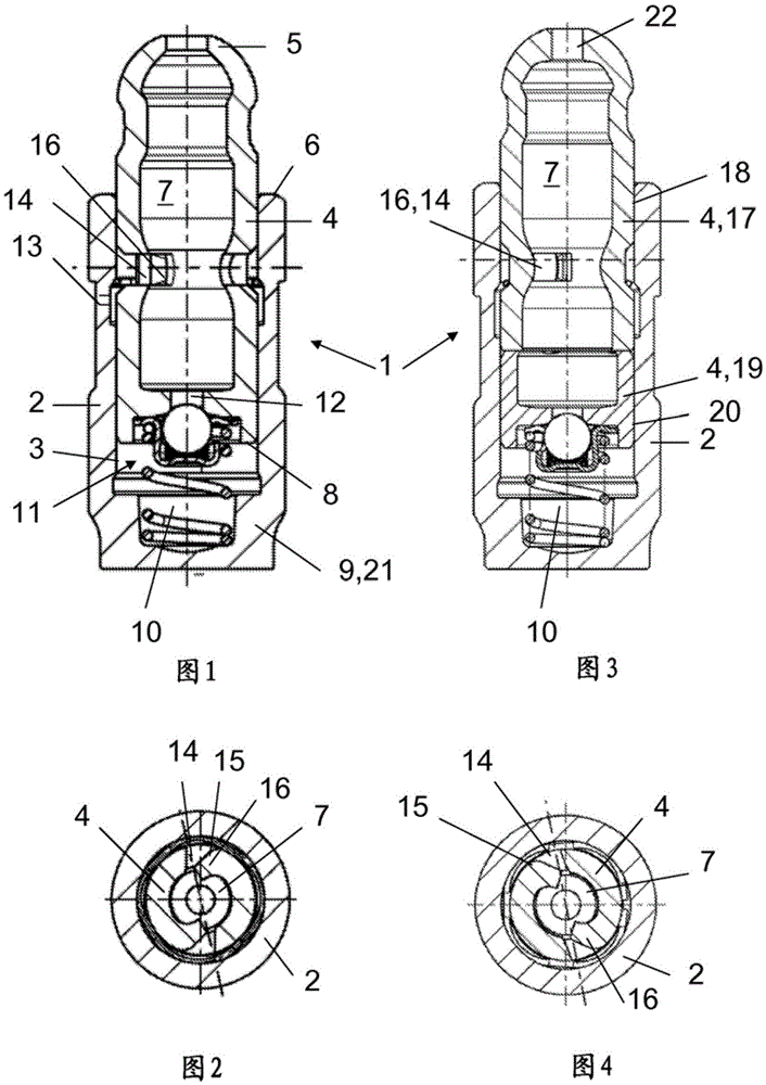
[0019] figure 1 A hydraulic support element 1 for a valve train of an internal combustion engine is disclosed. The support element 1 has a pot-shaped housing 2 which is closed by a base plate 21 in the region of its lower edge 9 . An inner element 4 axially displaceable therein is accommodated in the bore 3 of the housing 2 . The inner element protrudes with its spherical head 5 over the upper edge 6 of the housing 2 . The head 5 is intended to bear tightly against the drawbar.

[0020] The thin-walled and one-piece inner element 4 encloses a storage chamber 7 for hydraulic medium. Between the end face 8 of the inner element 4 facing away from the head 5 and the bottom plate 21 of the housing 2 there is a high-pressure chamber 10 for the hydraulic medium, said high-pressure chamber facing away via a passage (hole) 12 provided with a non-return valve 11 . It is connected to the storage chamber 7 in the end face 8 of the storage chamber.

[0021] like figure 2 Also shown ...


PUM


Abstract

A hydraulic support element (1) with a housing (2) is proposed, in the bore (3) of which an axially movable inner element (4) is received which protrudes with the head (5) thereof beyond an upper edge (6) of the housing (2) and surrounds a storage chamber (7) for hydraulic medium, wherein a high pressure chamber (10) for the hydraulic medium lies between a front (8), remote from the head (5), of the inner element (4) and a lower edge (9) of the housing (2), which high pressure chamber (10) is connected to the storage chamber (7) via a passage (12) in the remote front (8), which passage (12) is provided with a non-return valve (11), and wherein the inner element (4) has a passage (14) for the hydraulic medium, which passage (14) is fed by a supply (13) in the housing (2), is enclosed by the housing (2) and is formed by a window with a material cut (16) which protrudes in a door-like manner into the storage chamber (7) and is attached in one piece to a frame side (15) on said window.

Description

technical field [0001] The invention relates to a hydraulic supporting element, especially for a valve train of an internal combustion engine, the hydraulic supporting element has a housing, and a housing is accommodated in a hole of the housing, which can move axially relative to the housing. an inner element with its head protruding from the upper edge of the housing and enclosing a storage chamber for the hydraulic medium, wherein the high-pressure chamber for the hydraulic medium is located on the end face of the inner element facing away from the head and the housing Between the lower edge of the , said high-pressure chamber is connected with the storage chamber in the facing away end face via a passage provided with a non-return valve, and wherein the inner element has a power supply fed by an input in the housing and surrounded by the housing. At least one channel for hydraulic medium. Background technique [0002] A support element of this type is known from the tec...

Claims


Application Information

Patent Timeline
Patent Type & Authority Applications(China)
IPC IPC(8): F01L1/24
CPCF01L1/2405
Inventor 彼得·赛勒霍斯特·格雷迪约亨·布拉舍
Owner SCHAEFFLER TECH AG & CO KG
Why Eureka
Try Eureka