Gangway foot plate device
A technology of crossing boards and pedals, which is applied in the field of railway passenger cars, can solve the problems of sliding boards and unfavorable passage of passengers, and achieve the effect of improving safety
- Summary
- Abstract
- Description
- Claims
- Application Information
AI Technical Summary
Benefits of technology
Problems solved by technology
Method used
Image


Examples
Embodiment 1
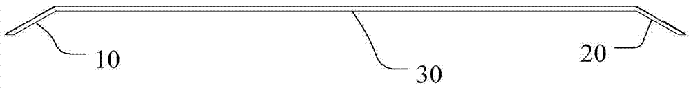
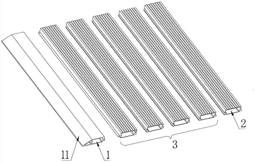
[0019] image 3 The schematic structural diagram of the crossing board device provided by Embodiment 1 of the present invention, such as image 3 As shown, the bridge device provided in this embodiment includes: a vehicle connecting plate 1, a platform connecting plate 2 and a plurality of pedal units 3, the vehicle connecting plate 1 is connected to the vehicle, the platform connecting plate 2 is connected to the platform, and a plurality of pedal units 3 The vehicle connecting plate 1 and the platform connecting plate 2 are sequentially connected, and each pedal unit 3 is horizontally hinged to the adjacent pedal unit 3 .
[0020] Specifically, the two ends of the bridge device provided in this embodiment are respectively a vehicle connecting plate 1 and a platform connecting plate 2, wherein the vehicle connecting plate 1 is placed in the vehicle compartment floor 100, and the platform connecting plate 2 is placed flat on the platform. A plurality of horizontally hinged pe...
Embodiment 2
[0026] Figure 5 It is a schematic structural diagram of the crossing plate device provided in Embodiment 2 of the present invention, as Figure 5 As shown, on the basis of the above-mentioned first embodiment, the transition board device further includes a folding plate 4, and the folding plate 4 is located between two adjacent pedal units 3 among the plurality of pedal units 3, and is connected to two adjacent pedal units respectively. The units 3 are connected, wherein the folding plate 4 and two adjacent pedal units 3 can be hinged or fixed. The folding plate 4 includes a first folding unit 41 and a second folding unit 42, the first folding unit 41 and the second folding unit 42 are hinged by a hinge shaft, and the rotation range between the first folding unit 41 and the second unit 42 0°~180°. By setting the folding plate 4, the crossing board device can be folded from the folding board 4. When the train is running or when the crossing board is not used, the crossing bo...
Embodiment 3
[0030] Image 6 It is a schematic structural diagram of the crossing board device provided by Embodiment 3 of the present invention, Figure 7 A schematic diagram of the use of the crossing board device provided in Embodiment 3 of the present invention, as shown in Figure 6 ~ Figure 7 As shown, on the basis of the above two embodiments, the transition plate device also includes: an end plate 5; the end plate 5 is connected to the platform connecting plate 2, and the connection method can be a chute connection, for example, the platform connecting plate 2 can be connected to the terminal The end that the plate 5 is connected is set as a chute or an axon, and the end that connects the end plate 5 and the platform connecting plate 2 is set as a corresponding matching axon or a chute, so that the end plate 5 can be set at the length of the platform connecting plate. Swipe in the direction.
[0031] Preferably, the top of the end plate 5 is an inclined surface 51 facing the plat...
PUM
 Abstract
Description
Claims
Application Information