Clamper for cleaning and degumming silicon chip

A silicon wafer cleaning and degumming technology, applied in sustainable manufacturing/processing, electrical components, climate sustainability, etc., can solve the problems of easy slipping of silicon wafers, high cost, low yield of silicon wafers, etc. Easy to operate, save labor, reduce cost input, and improve the effect of yield rate

Inactive Publication Date: 2009-04-15
KONCA SOLAR CELL
View PDF0 Cites 18 Cited by
  • Summary
  • Abstract
  • Description
  • Claims
  • Application Information

AI Technical Summary

Problems solved by technology

Since the lower clamp 1' and the connecting frame 2' are two independent parts, they must be installed and connected with bolts each time they are used. Different types of bonding boards 3' need to use different types of lower clamps 1' and connecting plates 2', so it is necessary to Using multiple types of lower fixtures and connecting plates is inconvenient to use, time-consuming and labor-intensive to operate, and the cost of investing in fixtures is relatively high
In addition, although the silicon wafer cleaning and degumming jig is provided with a partition plate 105', it cannot effectively fix the degummed silicon wafer. Usually, the partition plate 105' will slip after being subjected to the gravity of the silicon wafer. After the plate 105' is stressed, it slides in one direction, and the degummed and cleaned silicon wafers are more likely to slip and collide in the fixture, so that the silicon wafers are broken, and the yield rate of the cleaned and degummed silicon wafers is low.

Method used


Image

  • Clamper for cleaning and degumming silicon chip
  • Clamper for cleaning and degumming silicon chip
  • Clamper for cleaning and degumming silicon chip

Examples


Embodiment Construction

[0024] The specific implementation manners of the present invention will be further described in detail below in conjunction with the accompanying drawings.

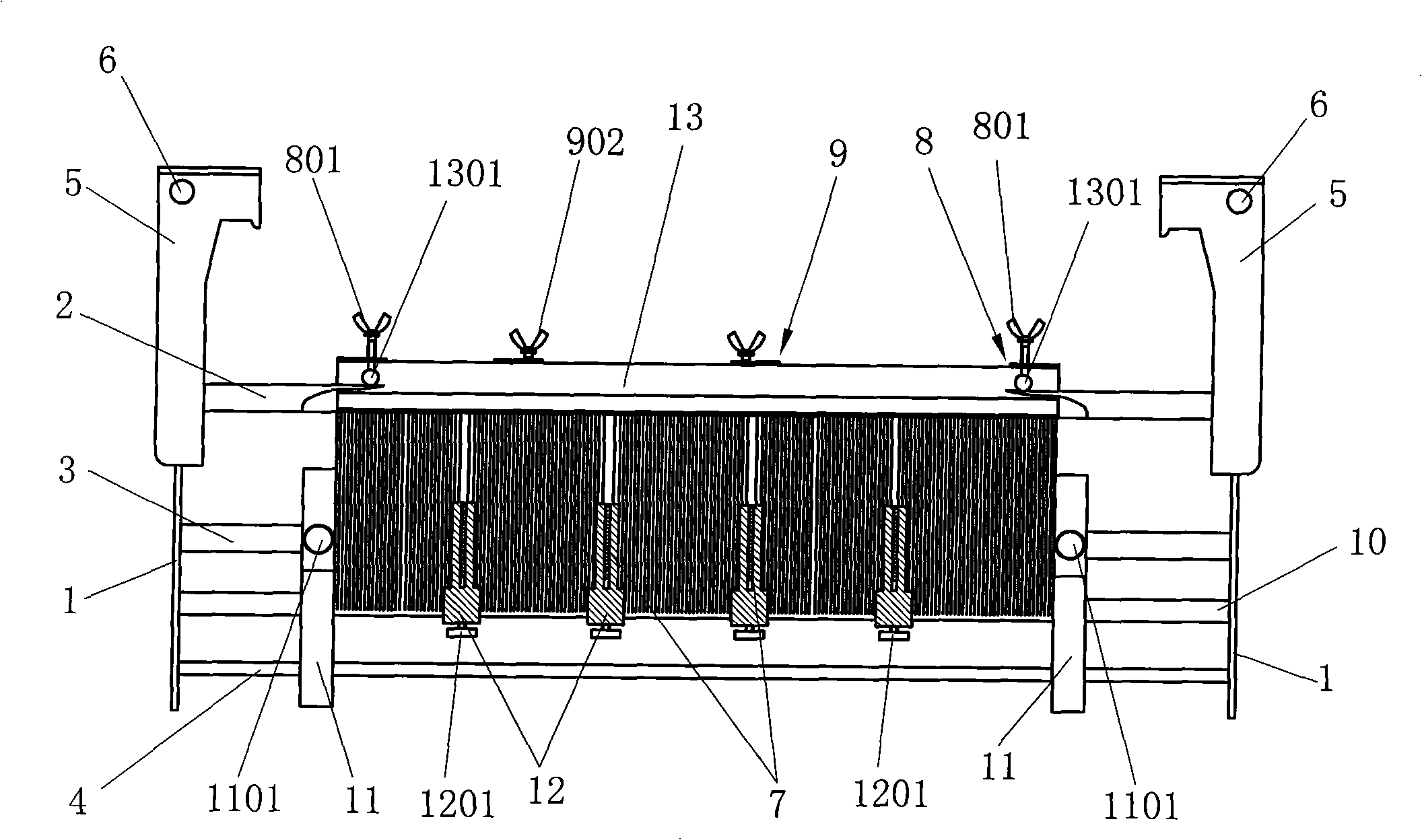
[0025] Such as image 3 , 4 , 5, the present invention comprises two side plates 1 and a pair of upper guide rods 2, partition plate guide rods 3 and lower guide rods 4 installed between the two side plates 1, on the partition plate guide rods 3 There are four partition plates 7 for clamping, and lifting hooks 5 are provided on both sides of the side plate 1, and handles 6 are connected between the lifting hooks 5. The lifting hooks 5 are used to lift the entire fixture in the cleaning and degumming machine, and the handles 6 are used as artificial Handles for carrying. The upper sliding sleeve of the upper guide rod 2 has two pairs of machine board fixing clips 8 and two pairs of machine board limit clips 9, the machine board fixing clips 8 and the machine board limit clips 9 can slide on the upper guide rod 2, The f...


PUM


Abstract

The invention relates to a cleaning and degumming clamp used during the process for producing a solar electric silicon wafer. The cleaning and degumming clamp comprises two lateral plates, and a pair of upper guide poles, a pair of partition plate guide poles and a pair of lower guide poles which are arranged between two lateral plates. Partition plates are clamped and hung on the partition plate guide poles. The cleaning and degumming clamp is characterized in that two pair of machine bonding plate fixing clamps and at least a pair of machine bonding plate position limiting clamps are sheathed on the upper guide poles in a slide way; the machine bonding plate fixing clamps are provided with bolts which clamp pins on a machine bonding plate; the machine bonding plate position limiting clamps are provided with adjusting collets which resist against two sides of the machine bonding plate; the adjusting collets are connected with the machine bonding plate position limiting clamps by screw thread; and the machine bonding plate position limiting clamps are provided with the bolts which fix the machine bonding plate position limiting clamps on the upper guide poles. A silicon wafer cleaning and degumming clamp disclosed by the invention can be fit for the different types of the machine bonding plates, is convenient to use and operate with labor saving and reduces the cost investment on clamp; in addition, a cleaned and degummed silicon wafer is upright on the lower guide poles and is not slipped and bumped easily to broke the silicon wafer, and the invention improves the good yield of the cleaned and degummed silicon wafer.

Description

technical field [0001] The invention relates to a jig, in particular to a cleaning and degumming jig used in the production process of solar electric silicon wafers. Background technique [0002] In the production process of silicon wafers for solar cells, the silicon rods are glued to the glass plate of the bonding machine. After being cut into silicon wafers, they need to be cleaned and degummed by a silicon wafer cleaning and degumming machine to separate the silicon wafers from the glass plate. Existing fixtures used in the process of cleaning and degumming silicon wafers, such as figure 1 , figure 2 As shown, the silicon wafer cleaning and degumming fixture is composed of two parts, the lower fixture 1' and the connecting frame 2'. The lower fixture 1' is composed of a pair of upper guide rods 102' and a partition plate guide rod between two side plates 101'. 103' and the lower guide rod 104', the adhesive plate 3' with the cut silicon wafers is hung on the upper gui...

Claims


Application Information

Patent Timeline
Patent Type & Authority Applications(China)
IPC IPC(8): H01L21/687H01L31/18
CPCY02P70/50
Inventor 杨风彦
Owner KONCA SOLAR CELL
Why Eureka
Try Eureka