[0011] Attached Figure 1-4 , To explain the present invention in detail.
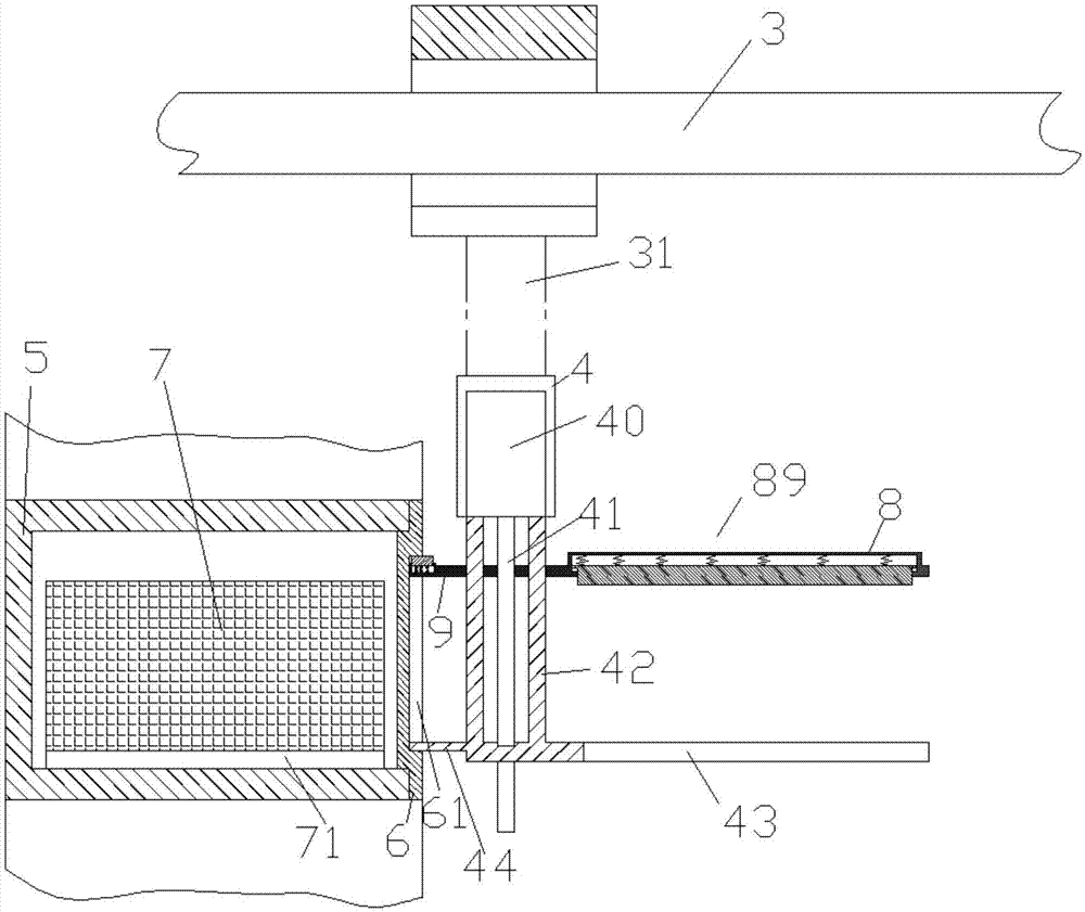
[0012] According to an embodiment, an intelligent warehouse logistics system with adjustable operating speed includes a control device 100, a storage cabinet device, and a material transport device, wherein the storage cabinet device includes a plurality of grippers arranged on the bottom surface of the container. Take the unit cabinet 5 of the material box 7 of the trough 71, the access opening of the unit cabinet 5 is installed with an openable and closable cover 6 with a holding slot 61 on the outer surface; the material transport device includes a driving mechanism 3 and A material box operating device connected to the drive mechanism 3 through a connecting rod 31 extending in the vertical direction. The drive mechanism 3 can drive the material box operating device to move in translation in the vertical direction and surround the connecting rod. The axis of 31 rotates and can move in the horizontal direction in the left-right direction and the front-rear direction. The material box operating device includes a carrier 4 fixedly connected to the connecting rod 31 and a carrier 4 arranged in the carrier 4 and connected with The operating drive motor 40 is connected with a screw 41 extending in the vertical direction, and the screw 41 is threadedly engaged with the screw hole in the movable plate member 89 including the cover joint 9 and the material box joint 8 that are integrally connected, so The two sides of the screw 41 are also provided with a guide bearing rod 42 whose upper end is fixedly connected to the supporting frame 4 and the lower end is fixedly connected to the fixed plate, so as to slidably fit with the guide hole in the movable plate 89 and used for bearing The load on the fixed plate, the fixed plate includes an integrally connected cover holding portion 44 for cooperating with the cover engaging portion 9 and for engaging with the bottom wall of the holding groove 61, and Used for cooperating with the material box engaging portion 8 and including a plurality of material carrying portions capable of extending into the plurality of grabbing grooves 71 for engaging the insertion claws 43 on the lower side of the material box 7; wherein The control device 100 can control the driving action of the drive mechanism 3, and can control the operation of the operation drive motor 40, and the control device 100 can also identify the code carrying device provided on the material box 7 The code recognition device 102 in 70 is communicatively connected and is communicatively connected to the user command input device 101. The control device 100 is also connected to a speed regulator 401, which is used to adjust the rotation speed of the operating drive motor 40 Therefore, it is possible to send a signal by operating the speed regulator 401 as needed, and control the rotation speed of the operating drive motor 40 through the control device 100.
[0013] Advantageously, a cover contact plate 92 that can be elastically moved up and down by the first elastic element 91 is provided on the upper side of the cover engaging portion 9 for engaging the upper top wall of the holding groove 61, and The material box contacting plate 81 that can move up and down elastically through the second elastic element 82 is provided in the lower side of the material box joint 8 for engaging the upper side of the material box 7, wherein when the When the opening and closing cover 6 is pulled out, the cover holding portion 44 contacts the bottom wall and the movable plate 89 moves upward so that the cover contact plate 92 is elastically displaced from the elastic equilibrium position. Large displacement and pressing on the upper top wall to cooperate with the cover gripping portion 44 to pull out the openable and closable cover 6; then the material box operating device rotates 180° around the axis , So that the insertion claw 43 and the material box contact plate 81 can be inserted into the unit cabinet 5 and the material box 7 is lifted, and then the movable plate 89 moves downward to make the material box The contact plate 81 is elastically displaced from the elastic equilibrium position by a second smaller displacement to press against the upper side of the material box 7 (e.g. image 3 As shown), at this time, the elastic displacement of the cover contact plate 92 from the elastic equilibrium position is the first smaller displacement, so that the cover contact plate 92 can still be pressed against the upper top wall (such as figure 2 (Shown), after that, the material box operating device again rotates 180° around the axis, so that the openable and closable cover 6 can be inserted back into the access opening, after which the movable plate 89 continues Move downwards, so that the material box contact plate 81 is elastically displaced from the elastic equilibrium position by the second larger displacement, and presses against the upper side of the material box 7 with greater force. At this time, the cover contacts The plate 92 is out of elastic contact with the upper top wall.
[0014] Refer again figure 2 , Where △9=first larger displacement-first smaller displacement, the length of △9 accounts for more than half of the total elastic deformation of the first elastic element, such as two-thirds or three-quarters.
[0015] Reference image 3 , Where △8=the second larger displacement-the second smaller displacement, the length of △8 accounts for more than half of the total elastic deformation of the second elastic element, for example, two-thirds or three-quarters.
[0016] Wherein, optionally, the total elastic deformation of the second elastic element may be greater than the total elastic deformation of the first elastic element.
[0017] Wherein, optionally, the elastic coefficient of the second elastic element may be greater than that of the first elastic element.
[0018] The above embodiments are only explanatory information for the present invention, and are not intended to limit the scope of the claims of the present invention.