Pipe-in-pipe faucet water control valve

A technology for faucets and water control valves, applied to multi-way valves, valve devices, engine components, etc., can solve complex problems, achieve low production costs and reduce production processes

Inactive Publication Date: 2017-05-03
HAIN YO ENTERPRISES
View PDF7 Cites 5 Cited by
  • Summary
  • Abstract
  • Description
  • Claims
  • Application Information

AI Technical Summary

Problems solved by technology

[0004] The problem to be solved by the present invention is: the known faucet body needs to be reserved with a water inlet chamber and a water outlet chamber, and there are secondary cold water inlet holes, hot water inlet holes, a fi...

Method used


Image

  • Pipe-in-pipe faucet water control valve
  • Pipe-in-pipe faucet water control valve
  • Pipe-in-pipe faucet water control valve

Examples


Embodiment Construction

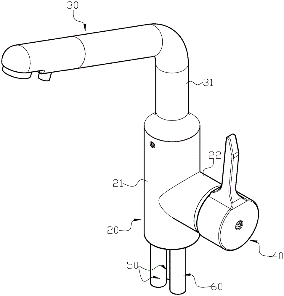
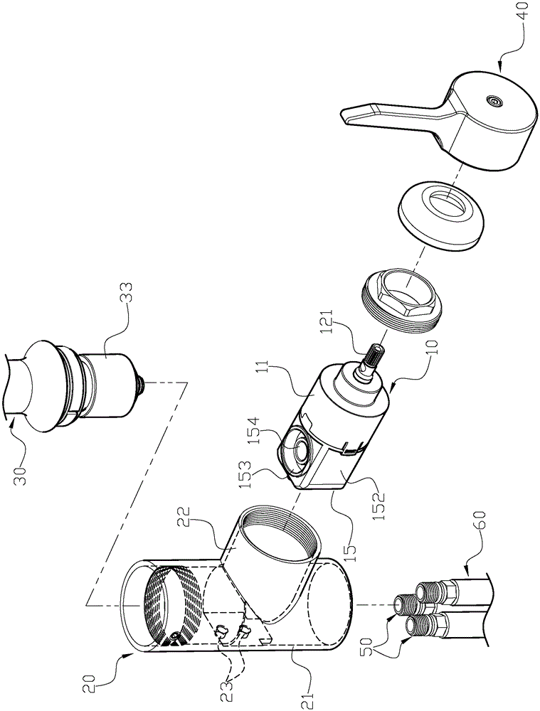
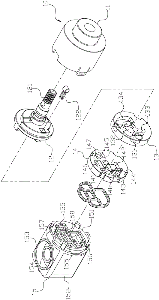
[0068] Usually according to the present invention, such as Figure 1 to Figure 7 As shown, the water control valve 10 is provided with a rotating seat 12, a movable valve plate 13 and a fixed valve plate 14 which are sequentially stacked in a valve housing 11, and the rotating seat 12 is also provided with an outwardly protruding valve. A valve stem 121 of the shell 11 is operated by the valve stem 121, and the movable valve piece 13 is embedded in the rotating seat 12 to rotate, and the change of the alignment relationship between the movable valve piece 13 and the fixed valve piece 14 can be used to control the faucet. Turn on and off the water, or change the mixing ratio of cold and hot water and the flow rate of the water. At the end of the valve housing 11, a combination of a valve seat 15 is used to block the fixed valve plate 14, the movable valve plate 13, the rotating seat 12, etc. Components fall out, and the water control valve 10 is used in conjunction with a fauce...


PUM


Abstract

The invention discloses a pipe-in-pipe faucet water control valve. According to the water control valve, a rotating base, a movable valve block and a fixed valve block which are sequentially overlapped are arranged in a valve shell, a valve rod extending out of the valve shell is arranged on the rotating base, the valve rod provides operation, the movable valve block is embedded through the rotating base and rotates and moves, and by means of the change of the position-aligning relation between the movable valve block and the fixed valve block, a faucet can be controlled to allow water to flow or not to flow, or the mixing proportion of cold water and hot water and the outlet water flow volume can be changed; a valve base combination at the tail end of the valve shell is used for stopping the fixed valve block, the movable valve block, the rotating base and other internal members from dropping out; and the water control valve is used in cooperation with the faucet, a water outlet pipe and a faucet handle.

Description

technical field [0001] The invention relates to a water control valve for a pipe-in-pipe faucet, in particular to a water control valve for a pipe-in-pipe faucet which utilizes changes in the alignment relationship of its internal valve plates to control the opening and closing of cold, hot water and filtered water. . Background technique [0002] Currently known pipe-in-pipe faucets (such as Figure 16 As shown), a water inlet chamber 71 and a water outlet chamber 72 are separately provided on the bottom surface and the top surface of a faucet body 70, and a valve cavity 73 is reserved on the side, so that the valve cavity 73 can provide a water control valve. 80 into the bearing, and the valve cavity 73 is provided with two cold and hot water inlet holes 74 penetrating down into the water chamber 71, a filtered water inlet hole 75, and a water outlet hole penetrating up through the water outlet chamber 72. Guide hole 76, a filtered water outlet guide hole 77, connect the ...

Claims


Application Information

Patent Timeline
IPC IPC(8): F16K11/074
CPCF16K11/074
Inventor 张家博
Owner HAIN YO ENTERPRISES
Why Eureka
Try Eureka