Discharging mechanism of bumper production line

An anti-collision bar and production line technology, which is applied to conveyors, conveyor objects, transportation and packaging, etc., can solve the problems of low unloading efficiency of the anti-collision bar, and achieve the effects of simple structure, reduced production cost, and improved transfer efficiency.

Active Publication Date: 2016-03-30
WUHU POWER TECH
View PDF6 Cites 4 Cited by
  • Summary
  • Abstract
  • Description
  • Claims
  • Application Information

AI Technical Summary

Problems solved by technology

[0003] Aiming at the deficiencies of the prior art, the present invention provides a blanking mechanism for the anti-collision bar production line, which automatically transfers the anti-collision bars on the production line to the transfer box by setting a positioning plate and a blanking plate, so as to solve the problem of the existing anti-collision bar production line. The problem of low rod unloading efficiency

Method used


Image

  • Discharging mechanism of bumper production line

Examples


Embodiment Construction

[0011] In order to deepen the understanding of the present invention, the present invention will be further described below in conjunction with the examples, which are only used to explain the present invention, and do not constitute a limitation to the protection scope of the present invention.

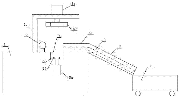
[0012] Such as figure 1 As shown, the present embodiment provides a blanking mechanism of a bumper production line, including a transport line 1, which drives the bumper to move, and the end of the transport line 1 is connected with an inclined downward blanking plate 2. A symmetrical positioning plate 3 is provided on the front conveyor belt 1 of the blanking plate 2, and a groove 4 is provided at the front end of the positioning plate 3. The length and width of the groove 4 correspond to the anti-collision bar , and a seat plate 6 controlled by a cylinder 5a to lift is arranged in the groove 4, and a transfer box 7 is connected below the blanking plate 2. Positioning grooves 8 are...


PUM


Abstract

The invention discloses a discharging mechanism of a bumper production line. The discharging mechanism comprises a transportation line which is used for driving a bumper to move, wherein the tail end of the transportation line is connected to a sloping downward discharging plate; symmetrical locating plates are arranged on a transportation belt in front of the discharging plate; grooves are formed in the front ends of the locating plates; the length and width of the grooves correspond to the length and width of the bumper; a baseplate controlled by an air cylinder to lift and drop is arranged in the grooves; the underneath of the discharging plate is connected to a transfer box; and the bumper moves after the two ends of the bumper are connected to the locating grooves by arranging the locating plates and the locating grooves, so that the bumper enters the transfer box quickly and stably, thereby preventing inconvenient transfer caused by disordered discharging of the bumper. The discharging mechanism is simple in structure and convenient to operate, and the production cost is reduced while the transfer efficiency is improved.

Description

technical field [0001] The invention relates to the field of anti-collision bar production, in particular to a rapid unloading mechanism for anti-collision bars. Background technique [0002] When the car is hit by the side, the door is easily deformed by the impact, which directly hurts the occupants in the car. In order to improve the safety performance of the car, many car companies place one or two very strong steel beams in the middle of the door interlayer on both sides of the car. , This is the side door anti-collision bar that is often said. The anti-collision effect of the anti-collision bar is that when the side door is hit, the strong anti-collision bar can greatly reduce the deformation of the side door, thereby reducing the damage of the car to the occupants of the car. The existing anti-collision bars are manually loaded and unloaded by workers in the production line, which is too inefficient and increases labor costs. Therefore, it is particularly important to...

Claims


Application Information

Patent Timeline
Patent Type & Authority Applications(China)
IPC IPC(8): B65G47/44B65G47/22B65G47/82
CPCB65G47/22B65G47/44B65G47/82B65G2201/0217
Inventor 陈昊吕名利杜立山王超陈存全丁尔胜刁先军郭一平郭治华韩友海
Owner WUHU POWER TECH
Why Eureka
Try Eureka