Deceleration strip capable of clear punishment on different vehicle speeds

A speed bump, clear technology, applied in the direction of roads, road signs, traffic signals, etc., can solve the problems of shortening the service life of speed bumps, loosening and shifting of speed bumps, etc., achieve smooth and continuous cross-sectional contour curves, prolong service life, and facilitate The effect of mastering

Active Publication Date: 2016-03-30
上海一起送网络科技有限公司
View PDF8 Cites 1 Cited by
  • Summary
  • Abstract
  • Description
  • Claims
  • Application Information

AI Technical Summary

Problems solved by technology

The frequent collision between the wheel and the speed bump will also cause the speed bump to loosen and shift, shortening the service life of the speed bump

Method used


Image

  • Deceleration strip capable of clear punishment on different vehicle speeds
  • Deceleration strip capable of clear punishment on different vehicle speeds
  • Deceleration strip capable of clear punishment on different vehicle speeds

Examples


Embodiment Construction

[0021] The present invention will be described in further detail below in conjunction with the accompanying drawings.

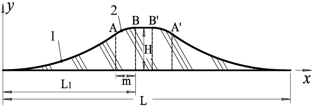
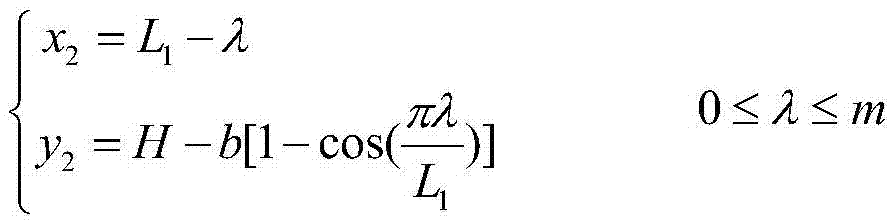
[0022] As shown in the figure, a deceleration belt with clear punishment for different speeds, the upper and lower ends of its cross section are horizontal straight lines, and the two sides are two symmetrical curves on the left and right. The curve consists of the first cosine curve segment 1 and the first cosine curve segment Two cosine curve segments 2; the first cosine curve segment 1 is tangent to the lower horizontal straight line, the second cosine curve segment 2 is tangent to the upper horizontal straight line, and the first cosine curve segment 1 is tangent to the second cosine curve segment 2 tangent.

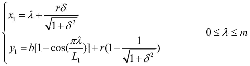
[0023] The parametric equation for the first cosine curve segment 1 is:

[0024] x 1 = λ ...


PUM


Abstract

The invention provides a deceleration strip capable of achieving clear punishment on different vehicle speeds. The upper end and the lower end of the cross section of the deceleration strip are provided with horizontal straight lines, and the two sides of the cross section are provided with a left curve and a right curve which are symmetrical; each curve is composed of a first cosine curve section (1) and a second cosine curve section (2), the first cosine curve section (1) is tangent to the lower-end horizontal straight line, the second cosine curve section (2) is tangent to the upper-end horizontal straight line, and the first cosine curve section (1) is tangent to the second cosine curve section (2). The deceleration strip has the advantages that strong bumping vibration punishment is applied to high-speed vehicles, the higher the vehicle speed is, the higher the punishment intensity is, and therefore a driver is reminded to learn a lesson and dares not to overspeed next time; low-speed vehicles can flatly drive through, and the riding comfort of the driver and passengers is better; the condition that an existing deceleration strip uniformly generates boring vehicle jumping bump and vibration impact no matter the vehicle speed is high or low is changed, induced noise is low, and the service life of vehicle parts and the deceleration strip is prolonged.

Description

technical field [0001] The invention relates to a deceleration belt used on roads, in particular to a road deceleration belt with clear punishment for different vehicle speeds, belonging to the field of deceleration belt design and manufacture. Background technique [0002] Vehicle speeding is the main cause of road traffic accidents, and the severity of the accidents is also the largest. As a passive speed control facility, road speed bumps can force passing vehicles to slow down, effectively curbing the incidence of traffic accidents and reducing the severity of accidents. However, the speed bumps currently used on the road have circular arcs or straight lines on both sides of the cross section. When people ride or drive past the speed bumps, no matter how high or low the speed is, they will generate jumping vibrations, which have a great impact on the performance and life of vehicle parts. An injury that also affects the ride comfort of the drivers and passengers, the ri...

Claims


Application Information

Patent Timeline
Patent Type & Authority Applications(China)
IPC IPC(8): E01F9/529
Inventor 祝海林邹旻史久伟
Owner 上海一起送网络科技有限公司
Why Eureka
Try Eureka