A stamping and compacting machine for floor foundation

A technology of tamping machine and stamping mechanism, which is applied in basic structure engineering, soil protection, construction, etc., can solve the problems of high noise on the job site, adverse effects of buildings, etc., and achieve flexible use, good construction environment, and wide application range Effect

Inactive Publication Date: 2018-02-06
WEIFANG UNIV OF SCI & TECH
View PDF4 Cites 0 Cited by
  • Summary
  • Abstract
  • Description
  • Claims
  • Application Information

AI Technical Summary

Problems solved by technology

With the ever-changing development of the construction industry, it is rare to rely entirely on manpower to compact the foundation of the floor. At present, centrifugal punching machines or hydraulic vibrators are used to tamp the foundation of the floor, but both use the principle of vibration to tamp the foundation of the floor. The site is relatively noisy, and at the same time, the vibration also brings adverse effects on the building itself

Method used


Image

  • A stamping and compacting machine for floor foundation

Examples


Embodiment Construction

[0016] The present invention will be further described through specific embodiments below in conjunction with the accompanying drawings.

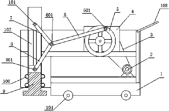
[0017] A stamping and compacting machine for floor foundations, comprising a frame 1, a power mechanism with a flywheel 5 and a booster stamping mechanism, the power mechanism and the booster stamping mechanism are both arranged on the frame 1, and the booster stamping mechanism includes a continuous Rod 6, toggle lever I7, toggle lever II8 and ram body 9, the ram body 9 is located in the slideway 102 vertically arranged inside the frame 1, and the inner wall of the slideway 102 is provided for guiding the rambody 9 to slide up and down along the slideway 102 The guide wheel 106 of the connecting rod 6, one end of the toggle lever I7 and the toggle lever II8 are hinged together through the pin II601, and the other end of the connecting rod 6 is hinged on the pin I501 on the outer edge of the flywheel 5, and the toggle lever I7 The other end...


PUM


Abstract

The invention discloses a terrace foundation stamping tamper which comprises a rack, a power mechanism with a flywheel and a force-amplifying stamping mechanism, wherein the power mechanism and the force-amplifying stamping mechanism are arranged on the rack; the force-amplifying stamping mechanism comprises a connecting rod, a toggle rod I, a toggle rod II and a tamping body; the tamping body is positioned in a slide path which is perpendicularly arranged on the inner part of the rack; the inner wall of the slide path is provided with a guide wheel for guiding the tamping body to slide up and down along the slide path; the connecting rod, one end of the toggle rod I and one end of the toggle rod II are hinged together by virtue of a pin roll II; the other end of the connecting rod is hinged to a pin roll I of a flywheel outer edge; the other end of the toggle rod I is hinged on the rack positioned above the tamping body by virtue of a pin roll III; and the other end of the toggle rod II is hinged to the upper end of the tamping body by virtue of a pin roll IV. According to the terrace foundation stamping tamper, the tamping body can generate great stamping force on the terrace foundation by use of relatively small power, so that compactness of the foundation reaches required standards, and therefore, the constructed terrace does not sink and deform forever.

Description

technical field [0001] The invention relates to the field of construction engineering equipment, in particular to a stamping and compacting machine for floor foundations. Background technique [0002] Before the construction of the building floor, the foundation under the floor needs to be compacted to prevent the floor from sinking and deforming under heavy pressure in the future. With the ever-changing development of the construction industry, it is rare to rely entirely on manpower to compact the foundation of the floor. At present, centrifugal punching machines or hydraulic vibrators are used to tamp the foundation of the floor, but both use the principle of vibration to tamp the foundation of the floor. The site is relatively noisy, and at the same time, the vibration also has an adverse effect on the building itself. Contents of the invention [0003] The purpose of the present invention is to provide a new type of compacting machine for floor foundations. By adopti...

Claims


Application Information

Patent Timeline
Patent Type & Authority Patents(China)
IPC IPC(8): E02D3/054
CPCE02D3/054
Inventor 李萍
Owner WEIFANG UNIV OF SCI & TECH
Why Eureka
Try Eureka