
Piston lubricating system for concrete cylinder, control method and device thereof, and pumping equipment

A concrete cylinder and piston lubrication technology, which is applied to the components, mechanical equipment, pump elements, etc. of the pumping device for elastic fluid, can solve the problem that the two-line lubricating oil distributor cannot work normally, increase the risk of wear of the concrete cylinder, Unable to lubricate the piston of the concrete cylinder, etc., to ensure the smooth lubrication of the piston, reduce the risk of wear, and prevent blockage

Active Publication Date:
View PDF8 Cites 1 Cited by
  • Summary
  • Abstract
  • Description
  • Claims
  • Application Information

AI Technical Summary

Problems solved by technology

[0004] The defect in the existing technology is that during the working process of concrete pumps and concrete pump trucks, the lubrication system mainly relies on the instantaneous pressure of the lubricating oil itself to flush the lubrication pipes. However, when the lubrication hole of the concrete cylinder is severely blocked, the double line The lubricant distributor is not working properly, which prevents the piston of the concrete cylinder from being lubricated, increasing the risk of wear on the concrete cylinder

Method used


Image

  • Piston lubricating system for concrete cylinder, control method and device thereof, and pumping equipment
  • Piston lubricating system for concrete cylinder, control method and device thereof, and pumping equipment
  • Piston lubricating system for concrete cylinder, control method and device thereof, and pumping equipment

Examples


Embodiment Construction

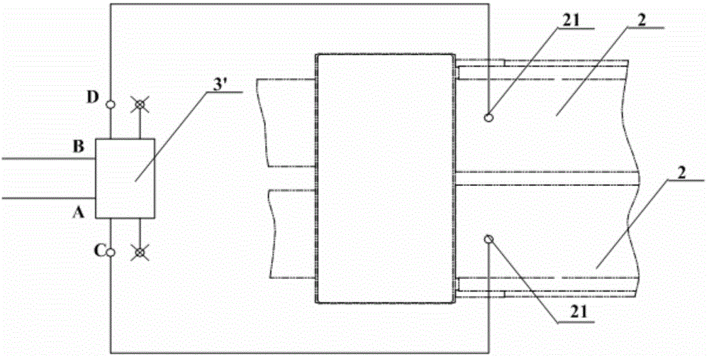
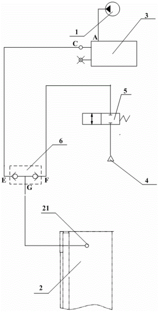
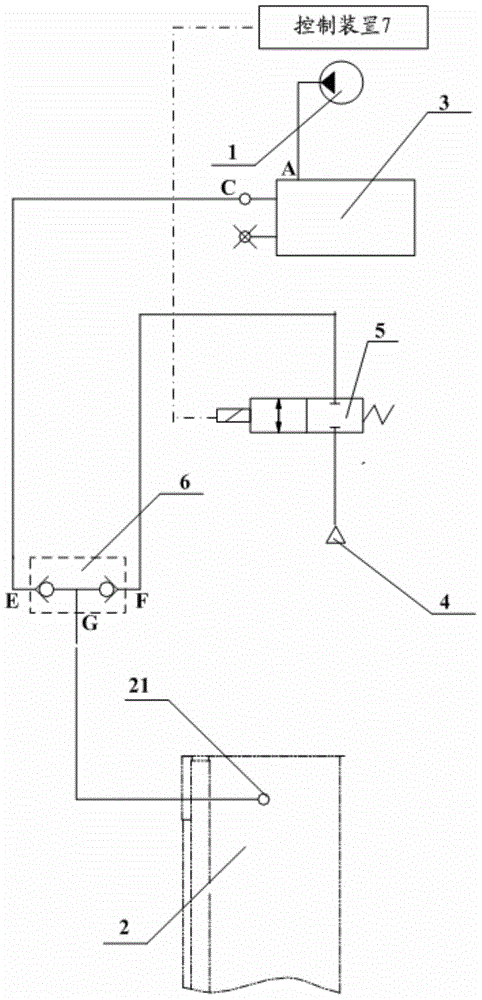
[0066] In order to prevent the blockage of the lubrication pipeline of the piston lubrication system of the concrete cylinder, thereby reducing the wear risk of the concrete cylinder, the embodiment of the present invention provides a piston lubrication system of the concrete cylinder, its control method, device and pumping equipment. In this technical solution, the piston lubrication system includes: an air source, a pressure-controlled on-off valve and an on-off valve. When the on-off valve is turned on, the gas from the air source enters the lubricating hole through the pressure-controlled on-off valve to flush the lubricating pipeline with gas. In this way, the blockage of the lubrication pipe and the lubrication hole is prevented, and the smooth lubrication of the piston of the concrete cylinder is guaranteed, thereby reducing the risk of wear of the concrete cylinder. In order to make the purpose, technical solution and advantages of the present invention clearer, the fol...


PUM


Abstract

The invention relates to the technical field of engineering machines, and discloses a piston lubricating system for a concrete cylinder, a control method and device thereof, and pumping equipment. Air flushing can be carried out on a lubricating pipeline, so that blockage of the lubricating pipeline and a lubricating hole is prevented, smooth lubrication on a piston of the concrete cylinder is guaranteed, and the abrasion risk of the concrete cylinder is further reduced. The piston lubricating system for the concrete cylinder comprises a lubricating oil pump, the concrete cylinder with the lubricating hole and a hydraulic lubricating device, wherein the hydraulic lubricating device is provided with an oil inlet and an oil outlet, and the oil inlet is connected with the lubricating oil pump. The piston lubricating system is characterized by further comprising an air source, a pressure-controlled switching valve and a switching valve, wherein the pressure-controlled switching valve is provided with a first inlet, a second inlet and an outlet, the first inlet is connected with the oil outlet of the hydraulic lubricating device, and the outlet is connected with the lubricating hole; an air inlet of the switching valve is connected with the air source, and an air outlet of the switching valve is connected with the second inlet; when the switching valve is connected, air of the air source enters the lubricating hole through the pressure-controlled switching valve.

Description

technical field [0001] The invention relates to the technical field of engineering machinery, in particular to a piston lubrication system for a concrete cylinder, a control method, a device and pumping equipment thereof. Background technique [0002] Concrete pumps and concrete pump trucks are widely used for concrete delivery in large concrete factories such as high-rise buildings, highways, and overpasses. It is mainly realized by the main oil pump, two main oil cylinders, two concrete cylinders, S valve and swing cylinder. The main oil pump controls two The pistons of the two main cylinders move in the opposite direction, and the pistons of the two concrete cylinders are driven to move in the opposite direction, so that the concrete is sucked into the rodless chamber of the concrete cylinder or the concrete in the rodless chamber is pushed into the inlet of the S valve. The feed port and the S valve are driven by the swing cylinder, and alternately communicate with the r...

Claims


Application Information

Patent Timeline
Patent Type & Authority Applications(China)
IPC IPC(8): F04B53/18
Inventor 陈远龙张培红张田李芳龙荣
Learn More