Reliquefaction system and process for liquefying bog by self-compression and expansion of bog

A compression expansion and reliquefaction technology, applied in the field of reliquefaction systems, can solve the problems of high energy consumption per unit volume of BOG, low process energy consumption, and many process equipment, etc., and achieves a high degree of automation, simple process, and low investment. Effect

Active Publication Date: 2018-01-05
CHINA NAT AIR SEPARATION ENG CO LTD
View PDF6 Cites 0 Cited by
  • Summary
  • Abstract
  • Description
  • Claims
  • Application Information

AI Technical Summary

Problems solved by technology

Currently, there are roughly two types of BOG reliquefaction processes: one is the nitrogen compression expansion refrigeration process, which uses nitrogen as the refrigerant, and the compression expansion provides cooling capacity for BOG; this process requires an independent nitrogen refrigeration cycle, and there are many process equipments And complex, relatively high energy consumption
The second is to use BOG direct condensation method. BOG is compressed by BOG compressor and mixed with LNG from the pump, and then condensed again, using the cold energy of LNG output from the LNG storage tank; this process has low energy consumption, but it is only suitable for The case of continuous LNG export
However, the technological process of this technical solution and the energy consumption per unit volume of BOG processed by the system are very high (3.45~7.655KW.h / Nm as pointed out in the patent 3 ), there is still a lot of room for optimization

Method used


Image

  • Reliquefaction system and process for liquefying bog by self-compression and expansion of bog

Examples


Embodiment Construction

[0031] The present invention will be further described in detail below in conjunction with the accompanying drawings and examples. The following examples are explanations of the present invention and the present invention is not limited to the following examples.

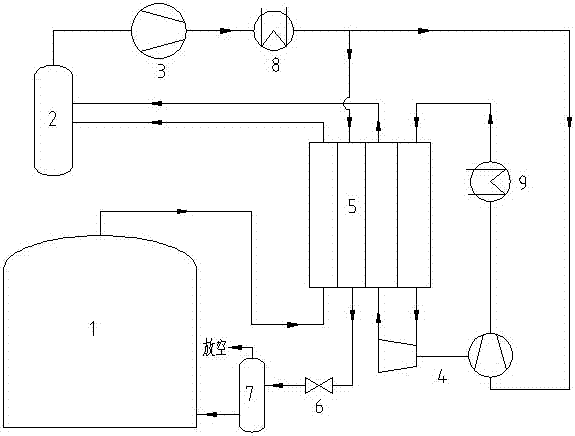
[0032] see figure 1 , the embodiment of the present invention uses BOG self-compression expansion to liquefy BOG reliquefaction system including LNG storage tank 1, BOG buffer tank 2, BOG compressor 3, turbo expander 4, heat exchanger 5, throttle valve 6, gas-liquid Separator 7 , first cooler 8 and second cooler 9 .

[0033] The heat exchanger 5 has a first flow path, a second flow path, a third flow path and a fourth flow path.

[0034] The first cooler and the second cooler are water coolers.

[0035] The BOG outlet of the LNG storage tank 1 communicates with the cold end inlet of the first flow channel of the heat exchanger 5 with a pipeline, and the hot end outlet of the first flow channel of the heat exchange...


PUM


Abstract

The invention relates to a reliquefaction system and technique for compressing expanded liquified BOG through the BOG. The number of equipment is decreased, the cost is reduced, energy consumption is low, the starting and stopping response speed is high, the operating flexibility is high, the load varying capacity is high, and the application range is wide. The BOG generated through a liquefied natural gas (LNG) storage tank is subjected to cold quantity recycling through a heat exchanger and then enters a BOG buffer tank to be converged with BOG serving as a cooling agent. Then the BOG enters a BOG compressor. The compressed BOG is divided into two parts through a first cooler. The first part of BOG enters the heat exchanger to be further cooled and liquified and then enters a gas-liquid separator through a throttling valve to be subjected to gas-liquid separation. The second part of BOG serves as the cooling agent of the first part of the BOG. The second part of BOG is pressurized through a turbine expansion machine, then enters a second cooler for water cooling and enters the heat exchanger to be cooled, and enters the turbine expansion machine to be expanded. The expanded BOG returns to the heat exchanger to supply cold quantity while being reheated for entering the BOG buffer tank to be converged with the first part of BOG. Circulation is conducted in this way.

Description

technical field [0001] The invention relates to a reliquefaction system and process for liquefying BOG by using BOG self-compression and expansion. Background technique [0002] As a high-quality and clean energy, natural gas has a high calorific value and less environmental pollution, and is considered to be the preferred energy source in the future. Atmospheric pressure liquefied natural gas (LNG), as a form of natural gas, its volume is only equivalent to 1 / 625 of the standard volume, which is very convenient for transportation and storage. With the development of the world and our country's economy, the demand for natural gas is increasing day by day. LNG is favored by countries all over the world for its high economy and flexibility. Due to the special storage conditions of LNG, a large amount of BOG gas is generated in LNG liquefaction plants, LNG transfer stations and LNG receiving stations. The main source is natural evaporation in LNG storage tanks and a large amou...

Claims


Application Information

Patent Timeline
Patent Type & Authority Patents(China)
IPC IPC(8): F25J1/02F25J3/00
Inventor 缪越张行东王丹
Owner CHINA NAT AIR SEPARATION ENG CO LTD
Why Eureka
Try Eureka