Test clamp for microwave power amplifier

A technology of microwave power and test fixture, applied in the field of machinery, to achieve the effect of convenient and quick adjustment

Inactive Publication Date: 2016-03-30
江苏博普电子科技有限责任公司
View PDF6 Cites 6 Cited by
  • Summary
  • Abstract
  • Description
  • Claims
  • Application Information

AI Technical Summary

Problems solved by technology

Since the size of the slide has no fixed parameters, the miniaturization of microwave power amplifier devices br

Method used


Image

  • Test clamp for microwave power amplifier
  • Test clamp for microwave power amplifier
  • Test clamp for microwave power amplifier

Examples


Embodiment Construction

[0021] The present invention will be further described below in conjunction with the accompanying drawings. The following examples are only used to illustrate the technical solution of the present invention more clearly, but not to limit the protection scope of the present invention.

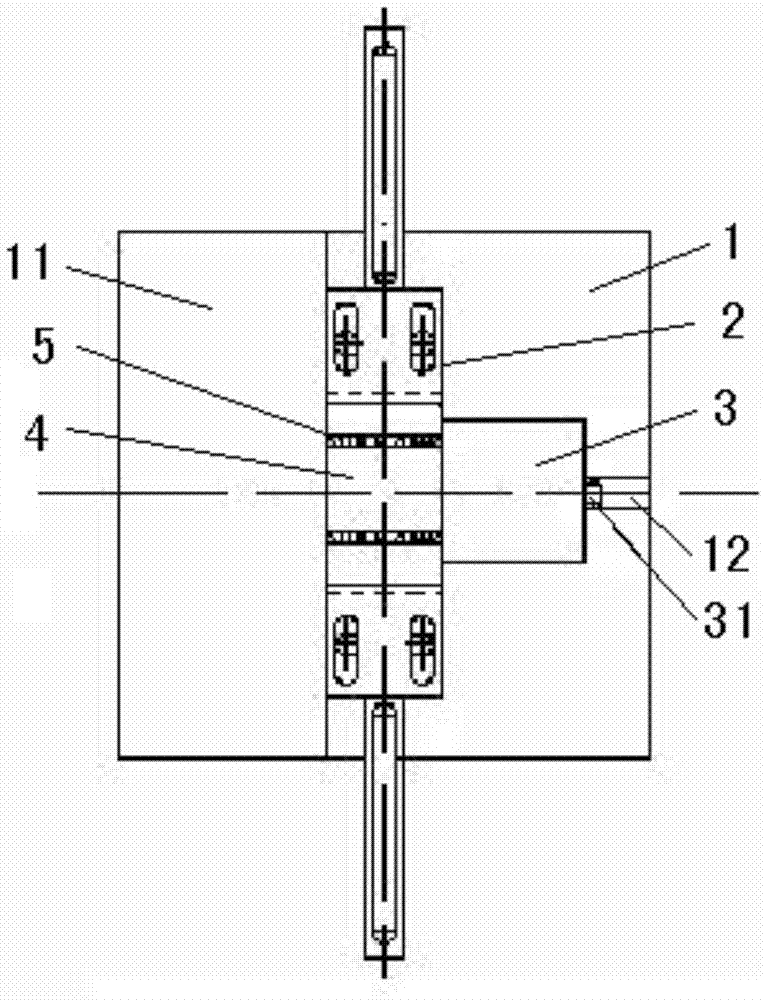
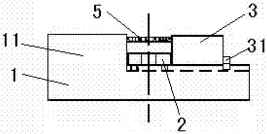
[0022] Such as figure 1 - figure 2 As shown, the test fixture for a microwave power amplifier of the present invention includes a base 1 for carrying a microwave power amplifier (hereinafter referred to as a slide), an adjusting pressure piece 2 that is adjustably installed on the base, and a clamping slide Clamp block 3.

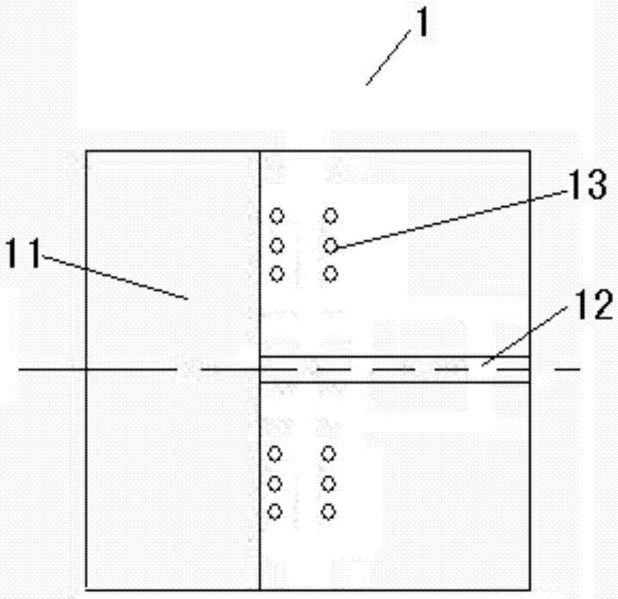
[0023] combine image 3 - Figure 4 One end of the base 1 has a positioning retaining wall 11 protruding from the upper surface of the base, and the other end upper surface of the base opposite to the positioning retaining wall 11 is equipped with a clamping block 3 that can be slidably adjusted toward the positioning retaining wall. The rectangular slide 4 is laid flat...


PUM


Abstract

The invention discloses a test clamp for a microwave power amplifier. The test clamp comprises a base, adjustment pressure sheets and a clamping block, wherein one end of the base is provided with a positioning retaining wall protruding out of the upper surface of the base, and the upper surface of the other end, opposite to the positioning retaining wall, of the base is provided with the slidable clamping block; the two sides of a microwave power amplifier chip are clamped by the clamping block and the positioning retaining wall; and the upper surface of the base at the other two sides of the chip is provided with multiple threaded holes cooperating with long grooves arranged in the adjustment pressure sheets, the adjustment pressure sheets are fixed to the upper surface of the base when connecting pieces pass through the long grooves of the adjustment pressure sheets at the corresponding same side and the threaded holes in the upper surface of the base, and the other two sides of the chip are each clamped and fixed by one adjustment pressure sheet. According to the invention, the test clamp for the microwave power amplifier can be adjusted according to the size of the microwave power amplifier, is applied to clamping tests of microwave power amplifiers with various dimensions and the specifications, is convenient and rapid to adjust and does not damage the chip.

Description

technical field [0001] The invention relates to a test fixture for a microwave power amplifier, which belongs to the technical field of machinery. Background technique [0002] Microwave power amplifiers play a vital role in wireless communication systems. With the development of communication technology, the requirements for microwave power amplifiers continue to increase. In applications that are sensitive to the volume of microwave power amplifiers, device miniaturization is becoming more and more important. Generally, traditional microwave power amplifiers are packaged in metal tubes, which are relatively easy to test. The miniaturized microwave power amplifier can be implemented in the form of a carrier chip instead of the traditional metal package. Since the size of the slide has no fixed parameters, the miniaturization of the microwave power amplifier device brings challenges to the test, especially there is no corresponding test fixture to clamp and test the microw...

Claims


Application Information

Patent Timeline
IPC IPC(8): G01R1/04
CPCG01R1/0425
Inventor 李贺关晓龙沈美根陈强
Owner 江苏博普电子科技有限责任公司
Why Eureka
Try Eureka