Eureka AIR delivers breakthrough ideas for toughest innovation challenges, trusted by R&D personnel around the world.

Method and system for acquiring high-precision timing signal

A timing signal, high-precision technology, applied in the direction of generating/distributing signals, etc., can solve the problem of providing additional high-precision clock chips

Active Publication Date: 2016-03-30
TCL CORPORATION
View PDF5 Cites 0 Cited by
  • Summary
  • Abstract
  • Description
  • Claims
  • Application Information

AI Technical Summary

Problems solved by technology

[0003] The purpose of the embodiments of the present invention is to provide a method and system for obtaining a high-precision timing signal, so as to solve the problem that an additional high-precision clock chip needs to be provided in the prior art for high-precision timing tasks

Method used


Image

  • Method and system for acquiring high-precision timing signal
  • Method and system for acquiring high-precision timing signal
  • Method and system for acquiring high-precision timing signal

Examples


Embodiment 1

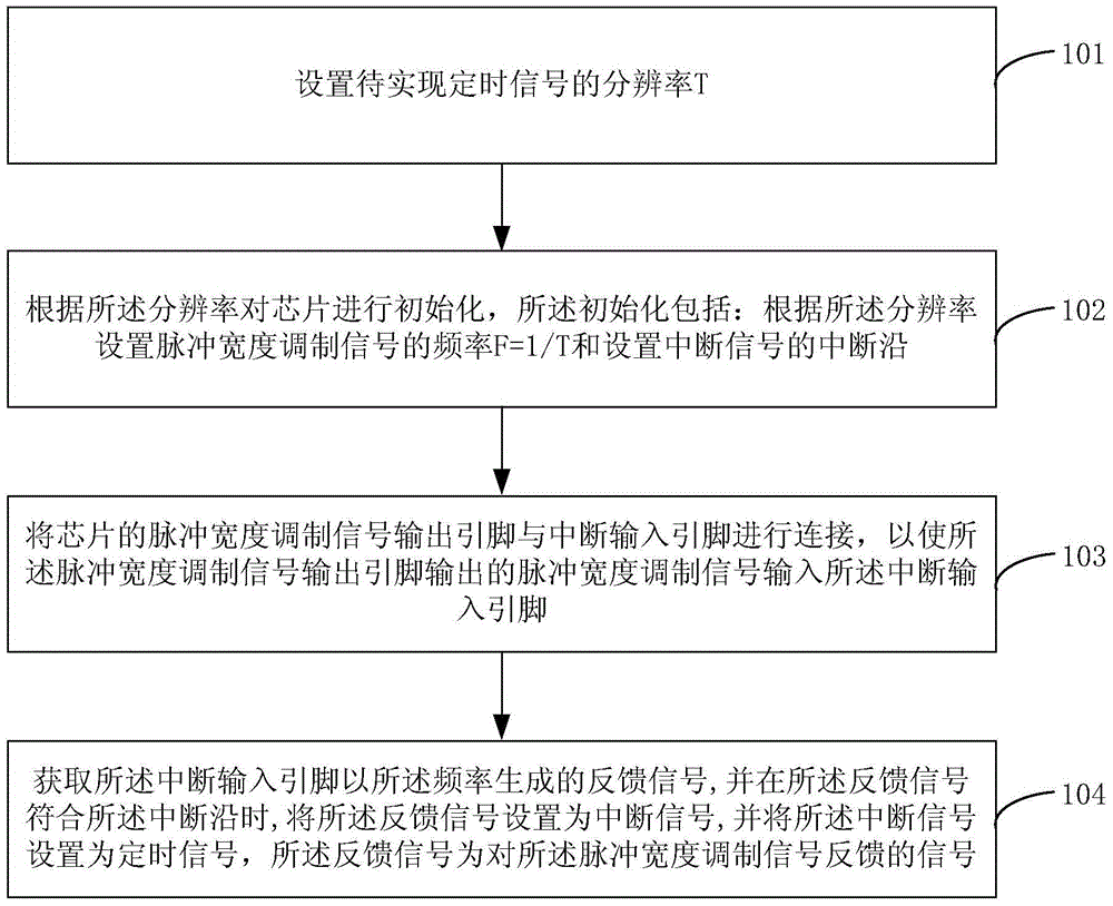
[0022] Such as figure 1 Shown is a flowchart of a method for obtaining a high-precision timing signal provided by an embodiment of the present invention, and the method includes the following steps:

[0023] In step S101, the resolution T of the timing signal to be realized is set.

[0024] In the embodiment of the present invention, the terminal first sets the resolution T of the timing signal to be realized, and the resolution T of the timing signal is close to or equal to the main clock frequency of the chip. Preferably, the resolution of the timing signal is microsecond level, such as: Assuming that the resolution of the timing signal to be implemented is 1 μs (microsecond), the terminal sets the resolution T of the timing signal to be implemented as 1 μs.

[0025] In step S102, the chip is initialized according to the resolution, and the initialization includes: setting the frequency of the pulse width modulation signal F=1 / T and setting the interrupt edge of the interru...
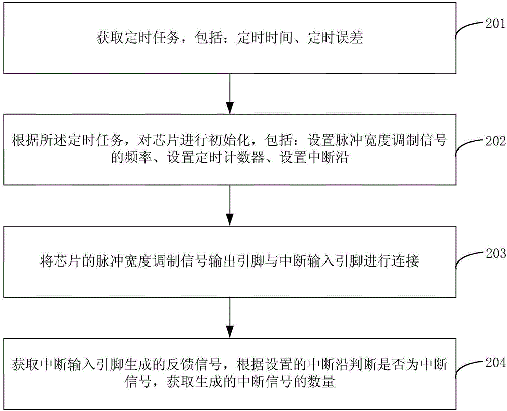
Embodiment 2

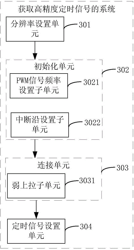
[0044] Such as image 3 Shown is a structural diagram of a system for obtaining a high-precision timing signal provided by an embodiment of the present invention. For ease of description, only parts related to the embodiment of the present invention are shown.

[0045]The system for obtaining high-precision timing signals specifically includes: a resolution setting unit 301, an initialization unit 302, a connection unit 303, and a timing signal setting unit 304. The specific functions of each unit are as follows:

[0046] The resolution setting unit 301 is configured to set the resolution T of the timing signal to be realized.

[0047] In the embodiment of the present invention, the resolution setting unit 301 first sets the resolution T of the timing signal to be realized. According to the needs of actual use, the resolution of the timing signal is usually at the microsecond level. For example: suppose the resolution of the timing signal to be realized If the rate is 1 μs (m...


PUM


Abstract

The present invention is applicable to the technical field of embedded chips, and provides a method and system for acquiring a high-precision timing signal. The method comprises: setting a resolution T of a to-be-realized timing signal; according to the resolution, initializing a chip; connecting a pulse width modulated signal output pin of the chip with an interrupt input pin; and acquiring a feedback signal generated by the interrupt input pin according to a frequency, setting the feedback signal as an interrupt signal when the feedback signal accords with an interrupt edge, and setting the interrupt signal as a timing signal, wherein the feedback signal is a signal fed back to a pulse width modulated signal. According to the method and system provided by the present invention, a terminal can receive the interrupt signal according to the frequency of a PWM signal, and set the interrupt signal as the timing signal, so that a timing function with a high resolution equal to the resolution of the PWM signal can be achieved.

Description

technical field [0001] The invention belongs to the technical field of embedded chips, and in particular relates to a method and a system for obtaining high-precision timing signals. Background technique [0002] Some embedded chips can only provide timers with secondary timing accuracy (such as milliseconds) relative to the main clock frequency of the chip (such as microseconds) due to system stability and the solidification of underlying resources. However, in the actual development process It is often necessary to use a more advanced timer that is close to or equal to the timing accuracy of the main clock frequency of the chip (such as microsecond level). The clock chip is used to handle this situation, which wastes manpower and material resources. Contents of the invention [0003] The purpose of the embodiments of the present invention is to provide a method and system for obtaining a high-precision timing signal, so as to solve the problem in the prior art that an a...

Claims


Application Information

Patent Timeline
Patent Type & Authority Applications(China)
IPC IPC(8): G06F1/06
Inventor 钟文涛张惠兴陈新刚
Owner TCL CORPORATION
Why Eureka
Eureka Blog
Learn More