Automatic assembly machine for wall control switch
What is Al technical title?
Al technical title is built by PatSnap Al team. It summarizes the technical point description of the patent document.
A technology of automatic assembly machine and control switch, applied in the direction of assembly machine, electric switch, manufacturing tool, etc., can solve the problems of low product qualification rate, low assembly efficiency, unstable product quality, etc., and achieve high degree of automation and high assembly efficiency. , The effect of stable product quality
Active Publication Date: 2016-03-30
DONGGUAN YI CHENG AUTOMATIC EQUIP
View PDF3 Cites 49 Cited by
Summary
Abstract
Description
Claims
Application Information
AI Technical Summary
This helps you quickly interpret patents by identifying the three key elements:
Problems solved by technology
Method used
Benefits of technology
Problems solved by technology
[0002] like figure 1 As shown, the wall control switch includes a single control type wall control switch and a double control type wall control switch, which can be composed of a base 01, a side terminal 02, a middle terminal 03, a rocker 04, a pressure plate 05, a bullet 06, Composed of spring 07 and transition piece 08, the traditional wall control switch uses manual or multiple equipment to assemble the various parts of the wall control switch, which has problems such as low assembly efficiency, unstable product quality, and low product qualification rate.
Method used
Image
Click on the blue label to locate the original text in one second.
Reading with bidirectional positioning of images and text.
Examples
Embodiment Construction
[0044] The following is the best example of the wall control switch automatic assembly machine described in the present invention, which does not limit the protection scope of the present invention.
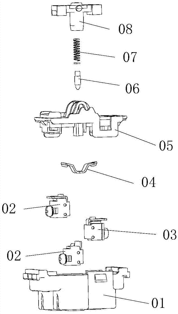
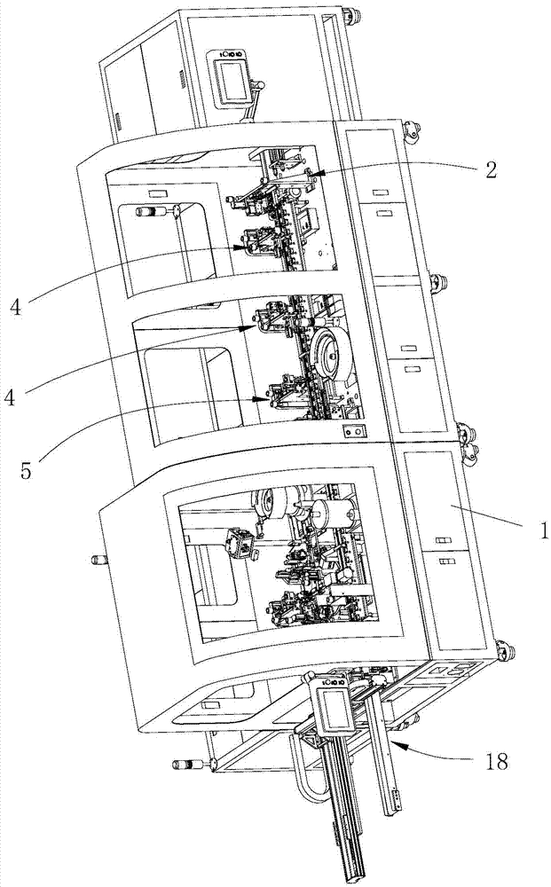
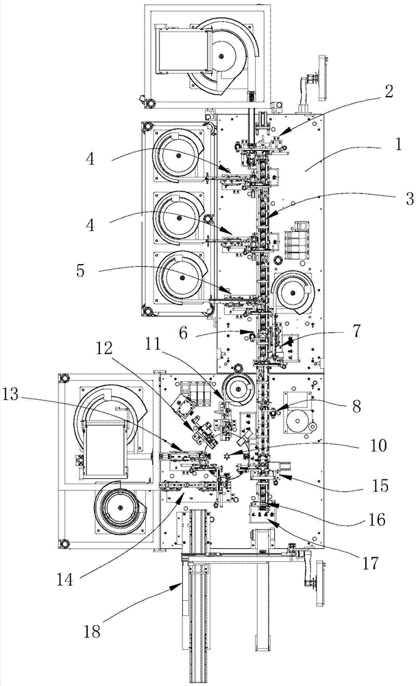
[0045] Please refer to figure 2 and image 3 , a wall control switch automatic assembly machine is shown in the figure, including a frame 1, a trough conveying device 3 is installed on the frame 1, and a base feeding mechanism for sending the switch base into the trough conveying device 3 2. One or two side terminal feed assembly mechanisms 4 for assembling the switch side terminals to the switch base, one middle terminal feed assembly mechanism 5 for assembling the middle terminals of the switch to the switch base, and one for the switch The seesaw feeding assembly mechanism 7 that the seesaw is assembled on the switch base, a turntable mechanism 10 with several clamps 9, a bullet feed mechanism 11 for placing the switch bullet on the clamp 9, and a bullet feed mechanism 11 fo...
PUM
Abstract
The invention discloses an automatic assembly machine for a wall control switch. The automatic assembly machine comprises a rack, a trough conveyer device, a base feeding mechanism, a side terminal feeding assembly mechanism, a medium terminal feeding assembly mechanism, a terminal missing detection mechanism, a wane feeding assembly mechanism, an oil adding mechanism, a rotary plate mechanism, a bullet feeding mechanism, a spring feeding assembly mechanism, a pressure plate feeding assembly mechanism, a transition part feeding assembly mechanism, a transition part component assembly mechanism, a switch conduction detection mechanism, a defective product discharge mechanism and a finished product discharge mechanism, wherein the trough conveyer device, the base feeding mechanism, the side terminal feeding assembly mechanism, the medium terminal feeding assembly mechanism, the terminal missing detection mechanism, the wane feeding assembly mechanism, the oil adding mechanism, the rotary plate mechanism, the bullet feeding mechanism, the spring feeding assembly mechanism, the pressure plate feeding assembly mechanism, the transition part feeding assembly mechanism, the transition part component assembly mechanism, the switch conduction detection mechanism, the defective product discharge mechanism and the finished product discharge mechanism are arranged on the rack. According to the automatic assembly machine for the wall control switch, various components of the wall control switch can be automatically assembled into a finished product of the wall control switch; the automatic degree and the assembly efficiency are high; the quality of the product is stable; and the qualified rate of the product can be effectively improved.
Description
technical field [0001] The invention relates to the technical field of switch automatic assembly equipment, and more specifically relates to an automatic wall control switch assembly machine. Background technique [0002] Such as figure 1 As shown, the wall control switch includes a single control type wall control switch and a double control type wall control switch, which can be composed of a base 01, a side terminal 02, a middle terminal 03, a rocker 04, a pressure plate 05, a bullet 06, Composed of spring 07 and transition piece 08, the traditional wall control switch uses manual or multiple equipment to assemble the various parts of the wall control switch, which has problems such as low assembly efficiency, unstable product quality, and low product qualification rate. Contents of the invention [0003] The object of the present invention is to overcome the above-mentioned defects in the prior art, and provide an automatic assembly machine for wall control switches w...
Claims
Application Information
Patent Timeline
Application Date:The date an application was filed.
Publication Date:The date a patent or application was officially published.
First Publication Date:The earliest publication date of a patent with the same application number.
Issue Date:Publication date of the patent grant document.
PCT Entry Date:The Entry date of PCT National Phase.
Estimated Expiry Date:The statutory expiry date of a patent right according to the Patent Law, and it is the longest term of protection that the patent right can achieve without the termination of the patent right due to other reasons(Term extension factor has been taken into account ).
Invalid Date:Actual expiry date is based on effective date or publication date of legal transaction data of invalid patent.