Supercharge Your Innovation With Domain-Expert AI Agents!

Diffuse type lightning rod

A lightning rod, diffusion type technology, applied in the direction of electrical components, circuits, corona discharge devices, etc., can solve problems such as inapplicability

Inactive Publication Date: 2016-03-30
GUANGXI NANNING BAILANSI SCI & TECH DEV
View PDF0 Cites 0 Cited by
  • Summary
  • Abstract
  • Description
  • Claims
  • Application Information

AI Technical Summary

Problems solved by technology

Since most of the lightning rods are fixed on the top of the building, it cannot be applied to a specific building

Method used


Image

  • Diffuse type lightning rod

Examples


Embodiment Construction

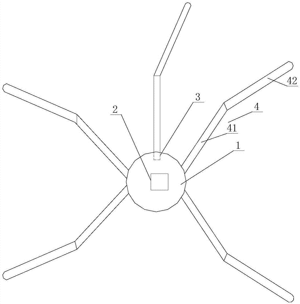
[0011] The present invention is described in further detail now in conjunction with accompanying drawing. These drawings are all simplified schematic diagrams, which only illustrate the basic structure of the present invention in a schematic manner, so they only show the configurations related to the present invention.

[0012] Such as figure 1 The shown diffused lightning rod includes a disc-shaped base body 1 and a lightning protection circuit 2 disposed in the base body. Five internally threaded holes 3 are provided on the circumference of the outer surface of the disc-shaped base body 1, and each internally threaded hole 3 is threadedly connected with a needle bar 4, and the needle bar 4 is formed by inserting a proximal section 41 and a distal section 42, and the angle between the proximal section 41 and the distal section 42 is 115°.

[0013] Inspired by the above-mentioned ideal embodiment according to the present invention, through the above-mentioned description cont...


PUM

PropertyMeasurementUnit
Angleaaaaaaaaaa

Abstract

The invention relates to a diffuse type lightning rod, comprising a disk-shaped base and a lightning-protection circuit arranged in the base; at least three inner threaded holes are arranged on the circumference of the outer side face of the disk-shaped base; a pin rod is in threaded connection with every inner threaded hole; the pin rods are formed by carrying out plug-in to near end sections and far end sections; the included angles between the near end sections and the far end sections are 110-120 degrees. The lightning rod using the design of the diffuse type lightning rod is suitable for special buildings.

Description

technical field [0001] The invention relates to the technical field of lightning protection, in particular to a diffused lightning rod. Background technique [0002] Lightning rod, also known as lightning rod, is a device used to protect buildings from lightning strikes. Install a metal rod on the top of a tall building, connect it with a metal plate buried in the ground with a metal wire, use the tip of the metal rod to discharge, gradually neutralize the electricity carried by the cloud layer and the electricity on the ground, so as not to cause ACCIDENT. The specifications of the lightning rod must comply with the GB standard, and the specifications of the lightning rod required for each level of lightning protection are different. Since most of the lightning rods are fixed on the top of the building, it cannot be applied to a specific building. Contents of the invention [0003] The technical problem to be solved by the present invention is: in order to overcome the...

Claims


Application Information

Patent Timeline
IPC IPC(8): H01T19/00H01T19/04
CPCH01T19/00H01T19/04
Inventor 黄兴英
Owner GUANGXI NANNING BAILANSI SCI & TECH DEV
Features
  • R&D
  • Intellectual Property
  • Life Sciences
  • Materials
  • Tech Scout
  • Unparalleled Data Quality
  • Higher Quality Content
  • 60% Fewer Hallucinations
Learn More