Supercharge Your Innovation With Domain-Expert AI Agents!

Control method for 10kV static var generator

A technology of static reactive power and control method, which is applied in reactive power compensation, reactive power adjustment/elimination/compensation, AC network circuit, etc. performance requirements, etc.

Active Publication Date: 2016-03-30
STATE GRID XINJIANG ELECTRIC POWER CO URUMQI ELECTRIC POWER SUPPLY CO +2
View PDF3 Cites 0 Cited by
  • Summary
  • Abstract
  • Description
  • Claims
  • Application Information

AI Technical Summary

Problems solved by technology

These traditional conventional control strategies are difficult to improve the stability of the system, and it is also difficult to achieve the system's requirements for dynamic performance, and cannot achieve ideal performance indicators.

Method used


Image

  • Control method for 10kV static var generator
  • Control method for 10kV static var generator
  • Control method for 10kV static var generator

Examples


Embodiment Construction

[0015] The control method of the 10kv static var generator is described in detail in conjunction with the accompanying drawings, which includes steps. The method includes the following steps:

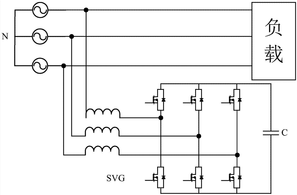
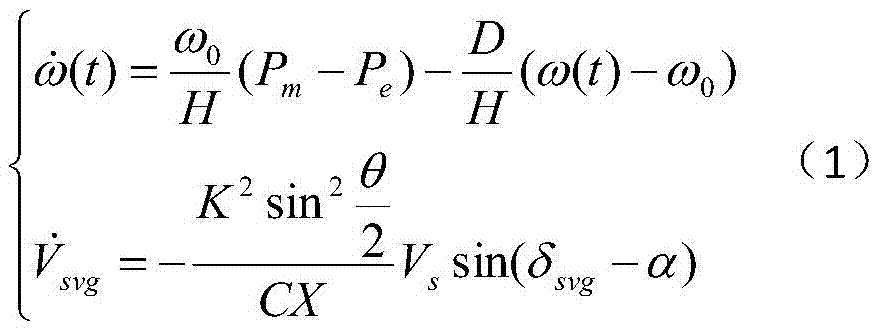
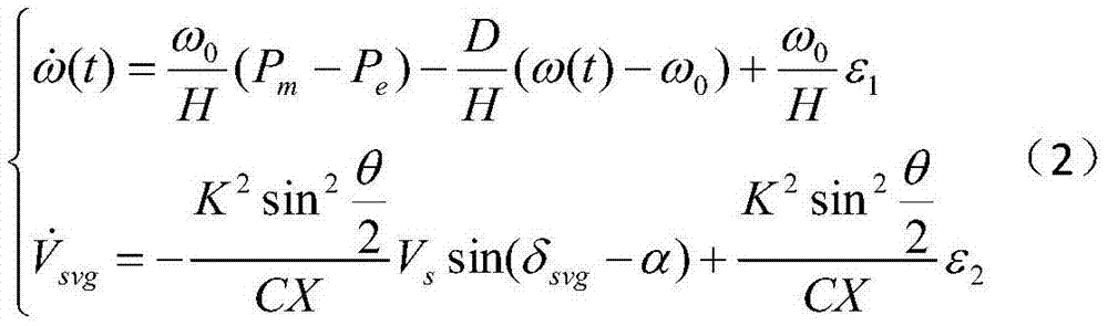
[0016] Step (1): Establish a mathematical model of the AC transmission system containing the static var generator;

[0017] The transmission line in the power system usually has a long distance, and it is necessary to consider the system grid voltage V when establishing a mathematical model s ∠α, the output voltage V of the static var generator svg and its fundamental component V svg ∠δ svg , line reactance X, DC side capacitor voltage U dc , the firing angle δ of the static var generator control pulse svg and conduction angle θ, generator rotor angular velocity ω and initial angular velocity ω 0 , the mechanical power P of the prime mover of the generator m and the electromagnetic power P of the generator e and the inherent damping coefficient D of the generator set, the inertia...


PUM


Abstract

The invention discloses a control method for a 10kv static var generator. By establishing a mathematical model of a system, based on flux-linkage control, the control method finally achieves control on a pulse triggering angle through a DSP (Digital Signal Processor) so as to achieve effects of not only inhibiting interference, but also achieving excellent static and dynamic performance.

Description

technical field [0001] The invention relates to a control method of a 10KV static var generator. Background technique [0002] Reactive power is very important to the operation of power supply system and load. In order to transmit active power, the power system requires a phase difference between the voltages at the transmitting end and the receiving end, which can be realized within a considerable range; in order to transmit reactive power, it requires another phase difference between the voltages at both ends, which can only be achieved within a certain range. within a narrow range. Not only the network elements of most power systems consume reactive power, but also most of the loads need to consume reactive power. The reactive power they need must come from somewhere in the network. Obviously, it is unreasonable and usually impossible to provide all these reactive powers by generators and transmit them over long distances. A reasonable method is to generate reactive p...

Claims


Application Information

Patent Timeline
Patent Type & Authority Applications(China)
IPC IPC(8): H02J3/18
CPCH02J3/18H02J2203/20Y02E40/30
Inventor 李永东孙伟郭良松周喜宾刘新宇艾比布勒·塞塔尔宋占党顾军原春亮黄擎陈兴王志远苏宁陈臻刘彪刘岩郑斌黄新民余英李武峰邓泽官王献丽鞠登峰张群狄谦薛利吴尚洁张冰婧陆东杰黄孟欣
Owner STATE GRID XINJIANG ELECTRIC POWER CO URUMQI ELECTRIC POWER SUPPLY CO
Features
  • R&D
  • Intellectual Property
  • Life Sciences
  • Materials
  • Tech Scout
  • Unparalleled Data Quality
  • Higher Quality Content
  • 60% Fewer Hallucinations
Learn More