Camera module, electrical bracket and assembly method and application thereof

A camera module and electrical technology, applied in electrical components, television, image communication, etc., can solve the problems of inability to do crimp connection and plug-in connection at the same time, the large package size of the camera module, and the high requirements for the size of the camera module

Active Publication Date: 2016-03-30
NINGBO SUNNY OPOTECH CO LTD
View PDF6 Cites 13 Cited by
  • Summary
  • Abstract
  • Description
  • Claims
  • Application Information

AI Technical Summary

Problems solved by technology

However, no matter which method is used for the substrate of the camera module, there is a problem, that is, the substrate can only be connected to each other in the upper and lower directions.
That is, a photosensitive chip is pasted on the upper surface of the substrate, and devices are connected on the lower surface of the substrate, but it is not possible to make a buckle connection and a plug-in connection at the same time.
Therefore, the camera module structure in the prior art cannot meet the needs of connecting different devices
[0012] Furthermore, with the improvement of the pixels of the camera module in the prior art, the area of ​​th

Method used


Image

  • Camera module, electrical bracket and assembly method and application thereof
  • Camera module, electrical bracket and assembly method and application thereof
  • Camera module, electrical bracket and assembly method and application thereof

Examples


Embodiment Construction

[0128] The following description serves to disclose the present invention to enable those skilled in the art to carry out the present invention. The preferred embodiments described below are only examples, and those skilled in the art can devise other obvious variations. The basic principles of the present invention defined in the following description can be applied to other embodiments, variations, improvements, equivalents and other technical solutions without departing from the spirit and scope of the present invention.

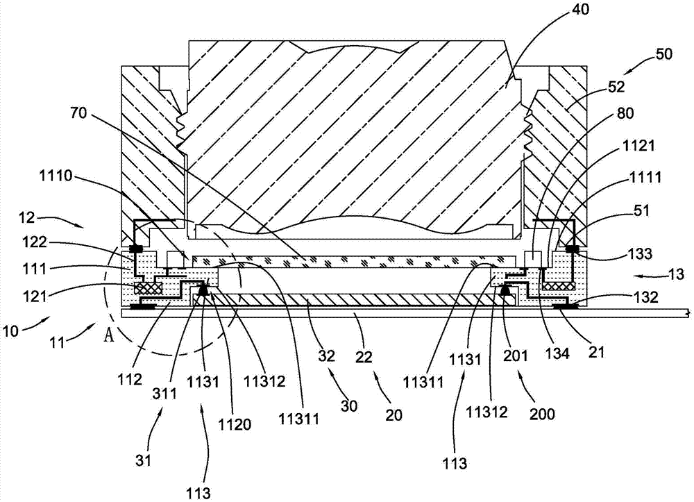
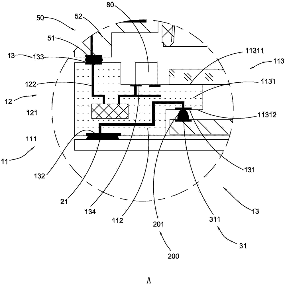
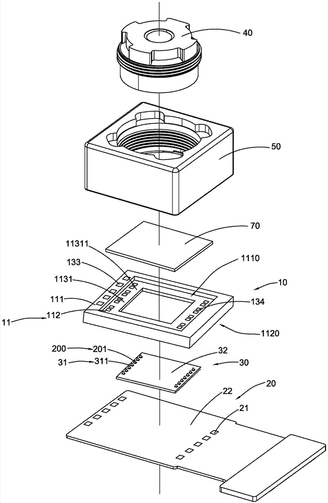
[0129] Figure 1 to Figure 3 A camera module according to a first preferred embodiment of the present invention is explained. The camera module includes an electrical support 10 , a flexible circuit board 20 , a photosensitive chip 30 , an optical lens 40 and a driving element 50 .

[0130] The optical lens 40 is mounted to the driving element 50, and the optical lens 40 can be driven by the driving element 50 to be suitable for autofocus. The flexible...


PUM


Abstract

The invention provides a camera module, an electrical bracket and an assembly method and an application thereof. The camera module comprises an optical lens, a photosensitive chip and the electrical bracket, wherein the optical lens is located above the photosensitive chip, and the photosensitive chip is electrically connected with the electrical bracket by implanting a metal ball, for example, a copper ball, so as to effectively save the cost and guarantee the electrical connection performance.

Description

technical field [0001] The present invention relates to the field of camera modules, and more specifically relates to camera modules, electrical brackets and their assembly methods and applications. Background technique [0002] With the rapid development of electronic products, their status in people's daily life is becoming more and more important. In order to realize the market demand of space saving and portability, electronic equipment is increasingly pursuing thinner and thinner, which requires the size of each component of electronic equipment, especially the thickness of each component to be smaller and smaller. For example, as one of the standard components of electronic equipment, The camera module also has a development trend of thinner and lighter. [0003] The structure of traditional COB (ChiponBoard) process camera module is assembled by soft and hard board, photosensitive chip, lens holder, motor drive and lens. Each electronic component is placed on the su...

Claims


Application Information

Patent Timeline
IPC IPC(8): H04N5/225
CPCH04N23/57H04N23/55
Inventor 王明珠王胤欢陈飞帆黄桢陈振宇郭楠
Owner NINGBO SUNNY OPOTECH CO LTD
Why Eureka
Try Eureka