MEMS microphone and formation method thereof

A microphone and diaphragm technology, applied in the field of MEMS, can solve the problems of low service life and poor performance of MEMS microphones

Active Publication Date: 2016-03-30
SEMICON MFG INT (SHANGHAI) CORP
View PDF5 Cites 6 Cited by
  • Summary
  • Abstract
  • Description
  • Claims
  • Application Information

AI Technical Summary

Problems solved by technology

[0006] The problem solved by the invention is that the existing MEMS microphones have low service life and poor performance

Method used


Image

  • MEMS microphone and formation method thereof
  • MEMS microphone and formation method thereof
  • MEMS microphone and formation method thereof

Examples


Embodiment Construction

[0055] In order to make the above objects, features and advantages of the present invention more comprehensible, specific embodiments of the present invention will be described in detail below in conjunction with the accompanying drawings.

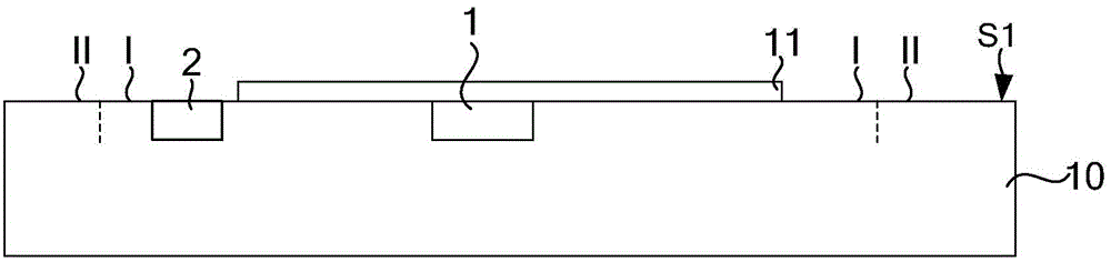
[0056] refer to image 3 , providing a first wafer 10, the front side S1 of the first wafer 10 has a first area I and a second area II, the second area II surrounds the first area I, and a conductive plate 11 is formed in the first area I. An integrated circuit (not shown in the figure) is formed in the first wafer 10 , the integrated circuit has a first electrode 1 and a second electrode 2 , wherein the conductive plate 11 is electrically connected to the first electrode 1 .

[0057] The conductive electrode plate 11 conducts electricity and will be used as the lower electrode plate of the MEMS microphone. In a specific embodiment, the material of the conductive plate 11 is Si, SiGe or Ge doped with ions, and may also be other metals suc...


PUM


Abstract

The invention provides an MEMS microphone and a formation method thereof. The MEMS microphone comprises a first wafer, where a conductive pole plate is formed; first support portions arranged around the conductive pole plate; first diaphragms lying across the first support portions respectively, wherein a gap is arranged between the conductive pole plate and the first diaphragms as well as the first support portions respectively, and the first support portions are conductive; at least one layer of second diaphragms arranged on the first diaphragms respectively, second support portions being arranged between the first diaphragms and the adjacent diaphragms in the second diaphragms respectively, the second support portions being conductive; a plurality of first through holes arranged in each second diaphragm; and a second wafer, the back surface of which is provided with a groove. The groove side wall is corresponding to the position of a second area, and the groove is corresponding to the position of a first area; a plurality of sound holes are formed in the bottom surface of the groove; in the position of the second area, the groove side wall is bonded with the front surface of the first wafer; and a gap is arranged between the bottom surface of the groove and the top-layer second diaphragm. The first through holes can diverge sound to enable damage to the first diaphragms and second diaphragms to be reduced.

Description

technical field [0001] The invention relates to the technical field of MEMS, in particular to a MEMS microphone and a forming method thereof. Background technique [0002] MEMS microphones using Micro-Electro-Mechanical System (MEMS, Micro-Electro-MechanicalSystem) technology have gradually replaced traditional microphones due to their miniaturization and lightness. [0003] refer to figure 1 , figure 2 , an existing MEMS microphone includes: a substrate 1, the substrate 1 has a front S1 and a back S2, and the substrate 1 has a back cavity 11 that runs through the front S1 and the back S2; a diaphragm 2 located at the front S1 of the substrate 1, the diaphragm 2 covers The back chamber 11; the support part 3 located on the diaphragm 2, and the conductive electrode plate 4 straddling the support part 3, there is a gap 5 between the conductive electrode plate 4 and the diaphragm 2, and the gap 5 corresponds to the position of the back chamber 11 , the back cavity 11 and th...

Claims


Application Information

Patent Timeline
Patent Type & Authority Applications(China)
IPC IPC(8): H04R19/04H04R31/00
Inventor 何昭文李曼曼
Owner SEMICON MFG INT (SHANGHAI) CORP
Why Eureka
Try Eureka