A soil dispensing device for combine machine

A technology for a combined working machine and a distribution device, which is applied in agricultural machinery and implements, applications, agriculture, etc., can solve the problems of complex structure design, high replacement cost, inconvenient maintenance, etc., and achieves low maintenance and replacement costs and simple structure. , to satisfy the effect of the diversion effect

Inactive Publication Date: 2016-04-06
CHONGQING MAODE AGRI DEV CO LTD
View PDF0 Cites 0 Cited by
  • Summary
  • Abstract
  • Description
  • Claims
  • Application Information

AI Technical Summary

Problems solved by technology

The structure design of the existing technology is relatively complicated when used, the maintenance is very inconvenient, and the replacement cost is high

Method used


Image

  • A soil dispensing device for combine machine
  • A soil dispensing device for combine machine

Examples


Embodiment 1

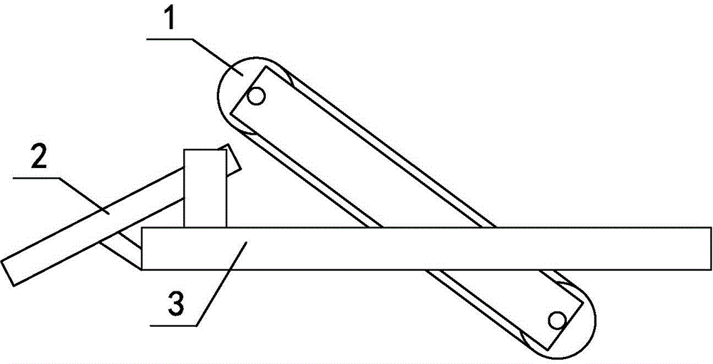
[0015] Such as figure 1 , figure 2 As shown, the soil distribution device for the combined operation machine includes a frame 3 and a conveyor 1 for conveying soil. The upper left end is installed on the frame 3 with a diverter tank 2 for diverting the soil, which is low in the left and high in the right. The diverter tank 2 is located on the left side of the conveyor 1. The depth of the diverter tank 2 is 50 mm, the width of the tank is 200 mm, and the length of the tank is 1500mm.

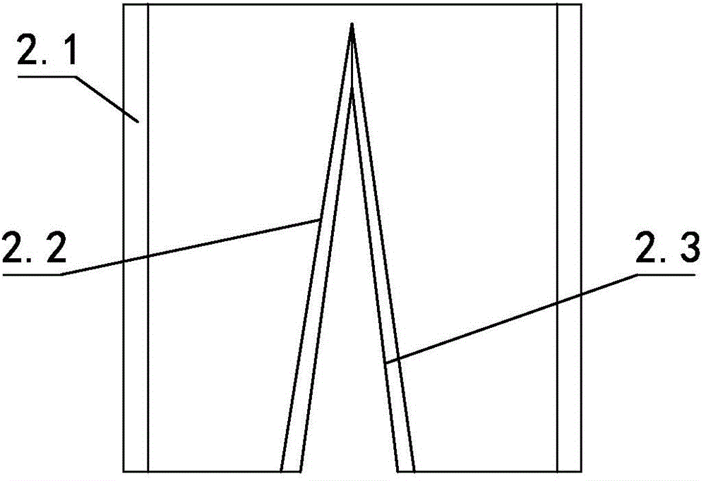
[0016] In this embodiment, the splitter tank 2 includes a tank body 2.1, a left splitter plate 2.2 and a right splitter plate 2.3 are arranged in the middle of the longitudinal direction of the tank body 2.1, and a left splitter plate 2.2 and a right splitter plate at the soil inlet of the splitter tank 2 are arranged. The splitter plates 2.3 are connected together, and the left splitter plate 2.2 and the right splitter plate 2.3 at the outlet of the splitter tank 2 are separated to form a tri...

Embodiment 2

[0020] Changes are made on the basis of Embodiment 1, and the changes are as follows:

[0021] The groove depth of the splitter groove 2 is changed to 80mm, the groove width is changed to 300mm, and the groove length is changed to 3000mm; the distance between the left splitter plate 2.2 and the right splitter plate 2.3 is changed to 50mm. Others are the same as embodiment one.

Embodiment 3

[0023] The groove depth of the splitter groove 2 is changed to 60mm, the groove width is changed to 250mm, and the groove length is changed to 2000mm; the distance between the left splitter plate 2.2 and the right splitter plate 2.3 is changed to 40mm. Others are the same as embodiment one.


PUM

PropertyMeasurementUnit
Groove widthaaaaaaaaaa
Slot lengthaaaaaaaaaa

Abstract

The invention relates to a soil dispensing device for a combine machine, and belongs to the technical field of soil dispensing. The device comprises a frame and a conveyor for conveying soil; the conveyor is obliquely mounted on the frame, thus being high in the left part and low in the right part, and a dispensing groove with a low left part and a high right part for dispensing soil is mounted on the frame corresponding to the left upper end of the conveyor; the dispensing groove is located at the left side of the conveyor, and has a groove depth of 50-80 mm, a groove width of 200-300 mm and a groove length of 1500-3000 mm. The inventive soil dispensing device is simple in structure and low in maintenance and replacement cost, and can realize a soil dispensing effect. The design of the reasonable size of the dispensing groove, the left dispensing plate and the right dispensing plate can successfully ensure the dispensing effect of the soil.

Description

technical field [0001] The invention relates to a soil distribution device for a combined operation machine, belonging to the technical field of soil distribution. Background technique [0002] With the development of science and technology, in China, a large agricultural country, the application of combined operating machines is becoming more and more extensive. Using it has many advantages, such as high operating efficiency and complete multiple operations at one time. At present, there is a combined operation machine, which is mainly used for planting wheat. During the planting process, the soil excavated from the ditch needs to be transported, and during the transport process, complete sowing and fertilization. When these two tasks are completed, The transported soil is then covered. The structural design of the existing technology is relatively complicated when used, the maintenance is very inconvenient, and the replacement cost is high. Contents of the invention ...

Claims


Application Information

Patent Timeline
IPC IPC(8): A01B49/06
Inventor 代克嘉
Owner CHONGQING MAODE AGRI DEV CO LTD
Why Eureka
Try Eureka