
Traction motor bearing taking-out device and method

A traction motor and extraction device technology, applied in electromechanical devices, manufacturing motor generators, electrical components, etc., can solve the problems of low bearing extraction work efficiency, easy bearing damage, and high bearing extraction cost, so as to improve the extraction work efficiency and bearing extraction. The effect of safe removal process and reduced bearing scrap rate

Inactive Publication Date: 2016-04-06
CHENGDU CRRC ELECTRIC MOTOR CO LTD
View PDF6 Cites 2 Cited by
  • Summary
  • Abstract
  • Description
  • Claims
  • Application Information

AI Technical Summary

Problems solved by technology

[0003] First, the operation of the operator is difficult, and the work efficiency of bearing removal is low, resulting in high cost of bearing removal
[0004] Second, the method of knocking the bearing with a copper hammer or a copper rod is clumsy. Not only is it easy to damage the bearing during the removal operation, but this knocking method also makes the work efficiency of the bearing lower and it is difficult to remove the bearing. The outer ring is completely removed from the bearing cover
[0005] Third, if the fit interference between the bearing chamber on the bearing end cover and the bearing outer ring is large, a large knocking force is required to remove the bearing outer ring from the bearing chamber on the bearing end cover. During the removal process, the bearing is easily damaged, and even leads to the scrapping of the bearing, which increases the application cost of the bearing product

Method used


Image

  • Traction motor bearing taking-out device and method
  • Traction motor bearing taking-out device and method
  • Traction motor bearing taking-out device and method

Examples


Embodiment Construction

[0027] In order to make the object, technical solution and advantages of the present invention clearer, the present invention will be described in detail below in conjunction with the accompanying drawings and specific embodiments. It should be understood that the specific embodiments described here are only used to explain the present invention, not to limit the present invention.

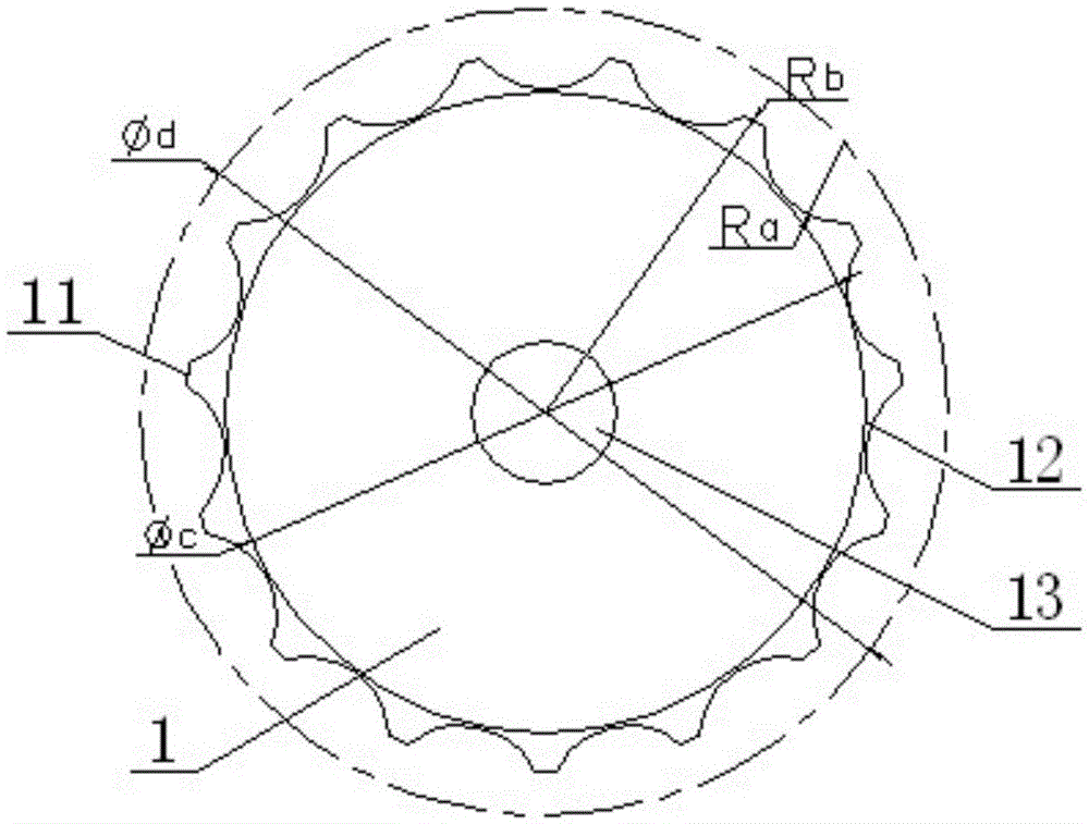
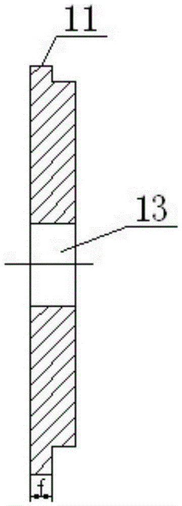
[0028] like figure 1 , figure 2 The shown traction motor bearing removal device mainly includes a toothed disc 1, and several convex teeth 11 are arranged on the circumferential direction of the ring toothed disc 1, and the convex teeth 11 and the toothed disc 1 are integrally formed to improve the convexity For the connection strength of the teeth 11, a groove 12 is provided between two adjacent protruding teeth 11.

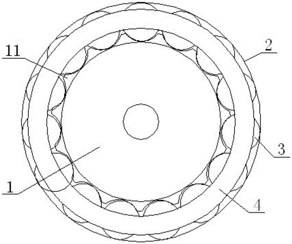
[0029] like image 3 , Figure 4 , Figure 5 As shown, the bearing outer ring 2, bearing roller 3, and bearing cage 4 of the traction motor bearing are connected into an integ...


PUM


Abstract

The invention provides a traction motor bearing taking-out device and method. The traction motor bearing taking-out device comprises a fluted disc (1). A plurality of convex teeth (11) are arranged in the circumferential direction of the fluted disc (1). A groove (12) is formed between every two adjacent convex teeth (11). When a traction motor bearing needs to be taken out, the grooves in the fluted disc are aligned to a bearing roller at first, the fluted disc is placed into the bottom of a bearing chamber on a bearing end cover, then, the fluted disc is rotated by a certain angle to enable the bearing roller to be hung on the convex teeth on the fluted disc, finally, pressure is applied to the fluted disc, and therefore a bearing outer ring is disengaged from the bearing chamber on the bearing end cover. By means of the traction motor bearing taking-out device and method, the narrow space between the bearing and the bearing end cover can be effectively utilized, installation is convenient, the whole bearing can be easily taken out of the bearing chamber on the bearing end cover, the whole bearing taking-out process is safe and reliable, the bearing taking-out difficulty and bearing rejection rate are greatly reduced, and the bearing taking-out working efficiency is improved.

Description

technical field [0001] The invention relates to the technical field of disassembly and assembly of traction motor bearings, in particular to a device and method for taking out traction motor bearings. Background technique [0002] The bearing outer ring, bearing rollers, and bearing cage of the existing traction motor bearing are connected into an integrated structure, and the bearing outer ring and the bearing chamber on the bearing end cover are fixedly connected by interference fit. Since the distance between the circular spigot surface of the bearing end cover and the outer surface of the bearing roller is very small, when the bearing outer ring is taken out from the bearing end cover by using an ordinary bearing removal device, such as a copper hammer or a copper rod, , there are the following problems: [0003] One is that the operation of the operator is difficult, and the work efficiency of bearing removal is low, resulting in high cost of bearing removal. [0004]...

Claims


Application Information

Patent Timeline
Patent Type & Authority Applications(China)
IPC IPC(8): B23P19/027H02K15/00
CPCB23P19/025B23P19/027H02K15/00
Inventor 李国辉范国安刘应伍胡豫奇
Owner CHENGDU CRRC ELECTRIC MOTOR CO LTD
Learn More