a tube device

A technology of pipe pulling device and telescopic device, which is applied in the direction of transportation and packaging, conveyors, conveyor objects, etc., can solve the problems of increasing manufacturing costs, pipeline superposition, and the effect of damaged frequency is not obvious, and achieve consistency of action Improvement, reduction of power unit, direct effect of transmission effect

Active Publication Date: 2017-11-07
ZHEJIANG KINGLAND & PIPELINE TECH
View PDF7 Cites 0 Cited by
  • Summary
  • Abstract
  • Description
  • Claims
  • Application Information

AI Technical Summary

Problems solved by technology

[0002] The pipe removal device is a very important sorting device on the steel pipe conveying production line. The pipe removal device in the prior art mainly uses a push connecting rod to drive the pipe removal rod hinged on it to flip, and then the steel pipe is moved by the inclined surface of the pipe removal rod. It can be realized by sliding out of the track, but this method has high requirements on the longitudinal force of the connecting rod. After a few weeks of production, the ordinary connecting rod will bend and deform in the middle due to the force on both ends, which will eventually affect the use effect. However, maintenance and repairs have to be carried out, which virtually increases the production cost and reduces the production efficiency; and the existing technology adopts the rollover method to pull the tube, the side driving capacity of this structure is insufficient, and many power devices need to be cascaded To cooperate with the action of the pulling tube structure increases the manufacturing cost. At the same time, the side driving method mainly adopts the pulling method, which is essentially the same as the push-pull method of the first prior art, except that there is an angle to disperse a certain force. However, the effect of reducing the frequency of damage is not very obvious. At the same time, both the existing first technical solution and the second technical solution will cause the force to be weakened due to the transmission length of the force, so that in the position where the relative transmission force is weak The turning speed of the pipe lever at the place is lower than that at other places, and the delay will affect the perpendicularity of the pipe after being transferred to the conveying direction of other conveying lines. In severe cases, the pipes will overlap

Method used


Image

  • a tube device
  • a tube device
  • a tube device

Examples


Embodiment Construction

[0018] The present invention will be described in further detail below in conjunction with the accompanying drawings.

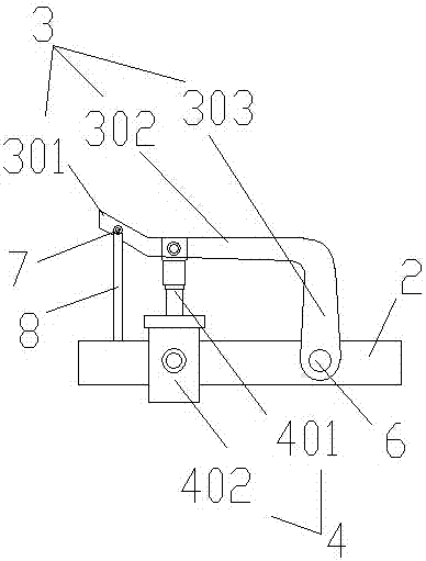
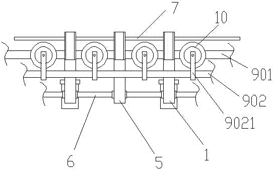
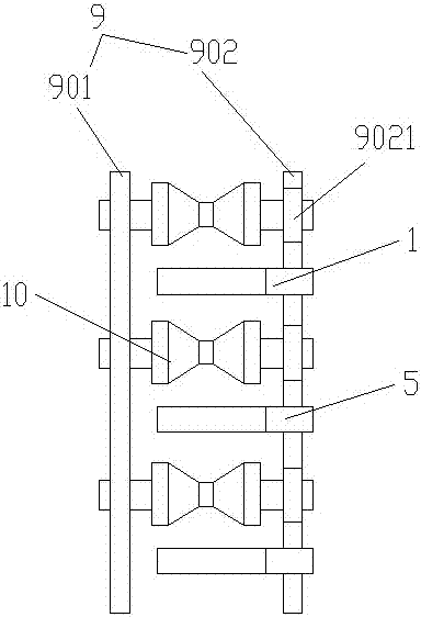
[0019] Such as Figure 1 to Figure 3 As shown, the embodiment of the present invention includes an active rod 1 and a fixed frame 2, and is characterized in that: the active rod 1 includes a tube rod 3 and a telescopic device 4, the tube rod 3 is hinged with the fixed frame 2, and the fixed frame 2 is connected with the telescopic device 4 is hinged, and the telescopic device 4 includes a telescopic rod 401 and a power part 402, and the telescopic rod 401 is hinged with the tube lever 3. The telescopic device 4 mainly adopts three forms, namely a hydraulic push rod, a pneumatic push rod and an electric push rod. The tube lever 3 includes a connection section 301, a horizontal section 302 and a tube section 303. The tube section 303 is arranged on the tube lever 3 near the hinged end of the telescopic lever 401 and the tube lever 3. The connection section 301...


PUM


Abstract

A pipe stirring device comprises a drive rod and a fixing frame. The pipe stirring device is characterized in that the drive rod comprises pipe stirring rods and a telescoping device, the pipe stirring rods are hinged to the fixing frame, the fixing frame is hinged to the telescoping device, the telescoping device comprises a telescopic rod and a power part, and the telescopic rod is hinged to the pipe stirring rods. By means of the structural design that connecting rods serve as rotating shafts, the push-pull transmission manner in the prior art is changed into the rotating manner low in damage rate, meanwhile, to improve the rotating synchronism, a connecting buckle between the connecting rods in the prior art is eliminated, cost is reduced, and meanwhile the effect is improved.

Description

technical field [0001] The invention belongs to the field of steel pipe production equipment, in particular to a pipe pulling device. Background technique [0002] The pipe removal device is a very important sorting device on the steel pipe conveying production line. The pipe removal device in the prior art mainly uses a push connecting rod to drive the pipe removal rod hinged on it to flip, and then the steel pipe is moved by the inclined surface of the pipe removal rod. It can be realized by sliding out of the track, but this method has high requirements on the longitudinal force of the connecting rod. After a few weeks of production, the ordinary connecting rod will bend and deform in the middle due to the force on both ends, which will eventually affect the use effect. However, maintenance and repairs have to be carried out, which virtually increases the production cost and reduces the production efficiency; and the existing technology adopts the rollover method to pull ...

Claims


Application Information

Patent Timeline
Patent Type & Authority Patents(China)
IPC IPC(8): B65G47/24
CPCB65G47/24B65G2201/0276
Inventor 史文华王遵圣卞忠景杨鑫伟叶百升张凯沈尧潘琪伟
Owner ZHEJIANG KINGLAND & PIPELINE TECH
Why Eureka
Try Eureka