
Magnetic latching relay for synchronous switch

A technology of magnetic latching relay and synchronous switch, which is applied in the direction of electromagnetic relay, relay, detailed information of electromagnetic relay, etc., can solve the problems of reducing contact pressure, reducing insulation strength, burning contacts, etc. The effect of improved consistency and shorter bounce time

Active Publication Date: 2016-06-15
HUIZHOU EVE TECH CO LTD
View PDF11 Cites 0 Cited by
  • Summary
  • Abstract
  • Description
  • Claims
  • Application Information

AI Technical Summary

Problems solved by technology

The magnetic latching relay requires a certain contact pressure to ensure stable contact contact, and reducing the magnetic force of the relay magnet will reduce the contact pressure, and the armature assembly will be pushed away by the electromagnetic repulsion during operation, causing the relay contact to be disconnected by mistake. Arcing burns out the contacts, rendering the relay completely useless
The method of shortening the stroke of the relay either reduces the distance between the contacts and reduces the insulation strength; or reduces the drop between the contacts and affects the life of the relay

Method used


Image

  • Magnetic latching relay for synchronous switch
  • Magnetic latching relay for synchronous switch
  • Magnetic latching relay for synchronous switch

Examples


Embodiment Construction

[0029] The present invention will be further described in detail below in conjunction with the embodiments and the accompanying drawings, but the embodiments of the present invention are not limited thereto.

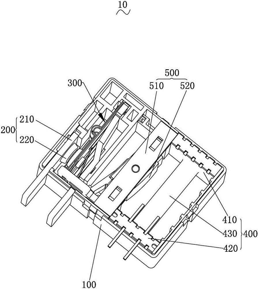
[0030] Such as figure 1 As shown, it is an internal structure diagram of a magnetic latching relay 10 for a synchronous switch according to an embodiment of the present invention. A magnetic latching relay 10 for a synchronous switch includes a relay base 100, and a static plate assembly 200 and a static disc assembly 200 are installed in the relay base 100. The blade assembly 200 contacts the connected movable blade assembly 300 . An electromagnetic assembly 400 and a permanent magnet assembly 500 are also installed in the relay base 100 .

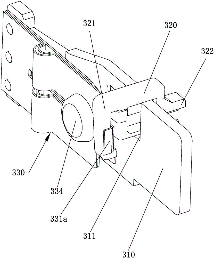
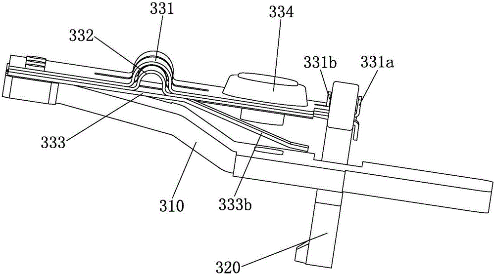
[0031] Such as figure 2 As shown, the moving piece assembly 300 includes: a moving piece 310, a push card 320 and a moving spring piece 330, one end of the moving spring piece 330 is fixedly connected to the moving piece 310, and...


PUM


Abstract

The invention discloses a magnetic latching relay for a synchronous switch. The magnetic latching relay comprises a relay base, wherein a stator plate assembly and a rotor plate assembly are arranged in the relay base; the rotor plate assembly is in contact connection with the stator plate assembly and comprises a rotor plate, a push card and a movable leaf spring; one end of the movable leaf spring is fixedly connected with the rotor plate; the other end of the movable leaf spring is driven by the push card to carry out reciprocating motion; a positioning through groove is formed in the rotor plate; the push card is arranged on the positioning through groove; the push card comprises a connection end and a push end; a positioning bayonet is arranged at the connection end; a push through groove is formed in the push end; the push card is connected with the movable leaf spring through the positioning bayonet; the movable leaf spring is provided with a movable contact; and the movable contact is arranged at one end, for reciprocating motion, near the movable leaf spring. The magnetic latching relay for the synchronous switch can shorten relay actuation time and pickup rebound time, so that the actuation time consistency of the relay is improved; and the relay meets the performance requirements of the synchronous switch.

Description

technical field [0001] The invention relates to the technical field of relays, in particular to a magnetic latching relay for a synchronous switch. Background technique [0002] The principle of the synchronous switch is to switch before the zero-crossing point of the alternating current, so that the contacts of the magnetic latching relay are just closed at the moment when the voltage crosses the zero point, so that the capacitor can be input without inrush current; the magnetic latching relay is cut off in advance before the zero-crossing point of the current, so that The magnetic latching relay is just disconnected at the zero crossing point of the current, so as to realize the arc-free cutting of the capacitor. [0003] The impact of the magnetic latching relay on the performance of the synchronous switch is mainly manifested in two aspects: 1. In the process of contact closure, due to the continuous reduction of the contact distance so that the insulation strength is in...

Claims


Application Information

Patent Timeline
Patent Type & Authority Applications(China)
IPC IPC(8): H01H50/58H01H50/16
CPCH01H50/16H01H50/58
Inventor 曾凯冯朝均罗楠李开波刘金成
Owner HUIZHOU EVE TECH CO LTD
Learn More