Elevator device

A technology of elevators and elevator cars, which is applied in the direction of elevators, transportation and packaging in buildings, and can solve the problem of narrow distance between the stop bolt and the wall of the mechanical room, and achieve the effect of easy construction work

Inactive Publication Date: 2016-04-06
HITACHI LTD
View PDF8 Cites 0 Cited by
  • Summary
  • Abstract
  • Description
  • Claims
  • Application Information

AI Technical Summary

Problems solved by technology

In this case, since the distance between the stopper bolt and the machine room wall becomes narrow in many cases, it becomes a bottleneck in determining the layout of the machine room.

Method used


Image

  • Elevator device
  • Elevator device
  • Elevator device

Examples


Embodiment Construction

[0026] The present invention relates to a stopper structure for suppressing a horizontal component force generated in a hoist of an elevator device.

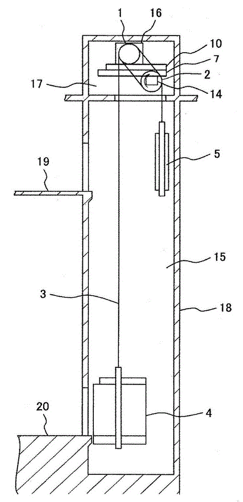
[0027] figure 1 Shows an overview of the entire elevator system.

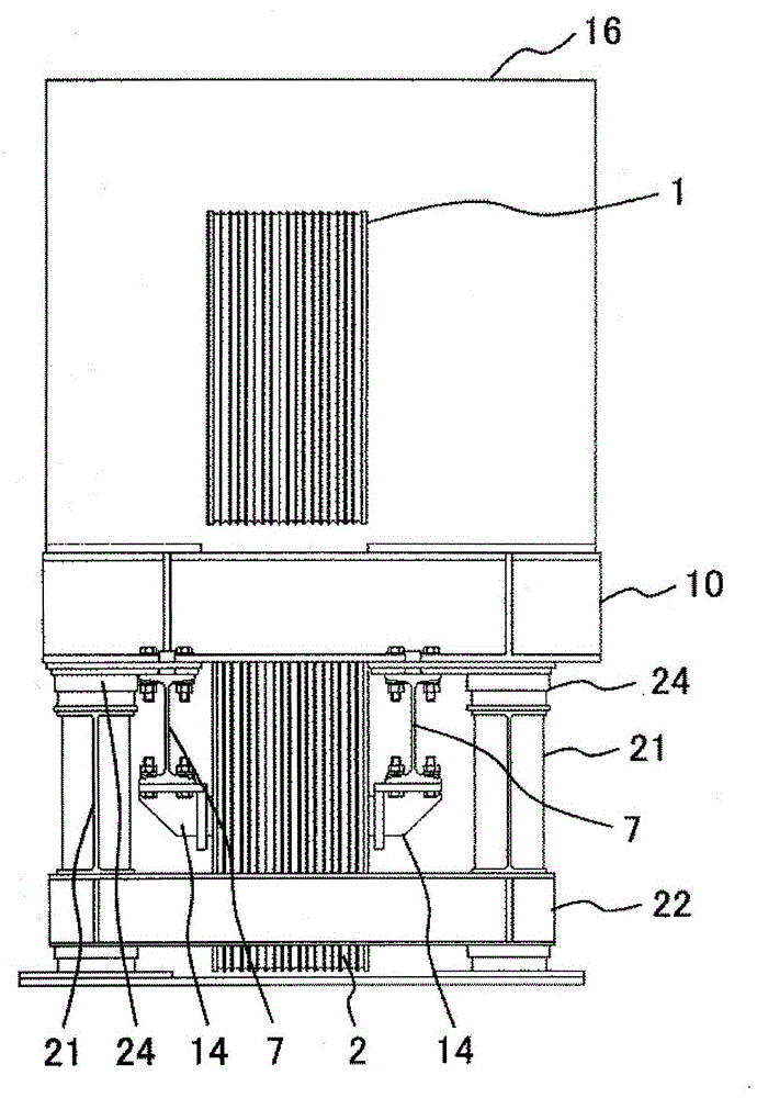
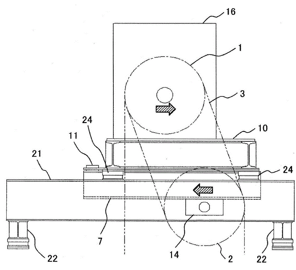
[0028] like figure 1 As shown, the elevator device has: an elevator car 4 and a counterweight 5 that move up and down in a hoistway 15 located in a building 18; a main sling 3 for suspending the elevator car 4 and a counterweight 5; And the winch 16 that makes the elevator car 4 and the counterweight 5 move up and down; the machine base 10 supporting the winch 16; the pulley beam 7 installed on the bottom of the machine base 10; the pulley bracket 14 installed on the bottom of the pulley beam 7; and The deflector pulley 2 is supported by the pulley bracket 14 and around which the main rope 3 is wound.

[0029] It should be noted that, in this embodiment, the winch 16 , the deflector wheel 2 , the machine base 10 , the pulley beam 7 and the pulley bracket 14 ar...


PUM


Abstract

The invention provides an elevator device. The device is provided with a component for overcoming the horizontal component of a winch without limitation of arrangement space of the winch in a machine chamber of the elevator device, and on-site construction operation is relatively easy. The elevator device is provided with an elevator car, a counterweight, a main sling for hanging the elevator car and the counterweight, a winch which is provided with rope wheels and makes the elevator car and the counterweight move up and down, a machine base supporting the winch, a pulley beam installed on the lower part of the machine base, a pulley bracket installed on the lower part of the pulley beam, and a deflective guide wheel which is supported by the pulley bracket and is winded with the main sling. A baffle block is arranged on the elevator car side on the upper part of the pulley beam. A baffle block patchhole is arranged on the elevator car side on the lower part of the machine base. A structure which makes the baffle block embedded in the baffle block patchhole is provided.

Description

technical field [0001] The present invention relates to an elevator installation. Background technique [0002] Patent Document 1 discloses a hoist vibration suppressing mechanism using a threaded rod and an elastic body as a support device for an elevator hoist that suppresses vibration generated from an elevator hoist from being transmitted to a machine table to cause the machine table to resonate. [0003] prior art literature [0004] patent documents [0005] Patent Document 1: Japanese Patent Laid-Open No. 2011-46481 [0006] The problem to be solved by the invention [0007] In the support device for the elevator hoist described in Patent Document 1, a space for installing and adjusting the lateral direction of the threaded rod (stop bolt) is required. On the other hand, on the side of the deflector wheel where the stopper is installed, basically a counterweight is placed. In this case, since the distance between the stopper bolt and the machine room wall becomes...

Claims


Application Information

Patent Timeline
Patent Type & Authority Applications(China)
IPC IPC(8): B66B11/04
Inventor 渡边桂哉松井裕
Owner HITACHI LTD
Why Eureka
Try Eureka