Electromagnetic lock, lock cylinder of electromagnetic lock and unlocking method for electromagnetic lock

An electromagnetic lock and lock cylinder technology, applied in the field of electromagnetic locks, can solve problems such as complex circuit structure, low service life of energy storage units, and limited life of locks, and achieve the effects of simple overall structure, safe and reliable use, and simple structure

Active Publication Date: 2016-04-06
SHANGHAI SHENGXIANG SCI & TECH
View PDF7 Cites 4 Cited by
  • Summary
  • Abstract
  • Description
  • Claims
  • Application Information

AI Technical Summary

Problems solved by technology

Since the energy storage of the energy storage unit takes a certain amount of time, the response time of the electronic lock is relatively slow
Secondly, the service life of the known energy storage unit is far lower than the electronic circuit and mechanical structure in the lock body. Once the service life of the energy storage unit is exhausted, the electronic lock will not be able to be used normally, so the life of the entire lock is limited.
In addition, the electronic lock taught by this invention patent requires a mechanical force provided by the motor and a linkage mechanism that transmits the mechanical force to realize the unlocking and locking of the lock, which increases the complexity of the internal structure of the lock, while the linkage mechanism that transmits the mechanical force Wear and tear of the motor, brush aging, stuck, wear, poor contact and damage to the deceleration mechanism will also lead to a further reduction in the overall life of the electronic lock
In addition, considering that the volume of the motor with corresponding output power is relatively large, this will lead to an increase in the volume of the lock, and the application range is limited
Finally, the signal control circuit taught by the invention includes a signal / power separation unit, a signal shaping unit, a signal superposition unit, a voltage stabilizing unit, an energy storage unit, etc., and its circuit structure is complex, making it difficult to miniaturize the lock

Method used


Image

  • Electromagnetic lock, lock cylinder of electromagnetic lock and unlocking method for electromagnetic lock
  • Electromagnetic lock, lock cylinder of electromagnetic lock and unlocking method for electromagnetic lock
  • Electromagnetic lock, lock cylinder of electromagnetic lock and unlocking method for electromagnetic lock

Examples


Embodiment Construction

[0045] The following description is disclosed to enable any person skilled in the art to make and use the invention. The preferred embodiments provided in the following description are only examples and modifications obvious to those skilled in the art, and they are not intended to limit the scope of the present invention. The general principles defined in the following description may be applied to other embodiments, alternatives, modifications, equivalent implementations and applications without departing from the spirit and scope of the invention.

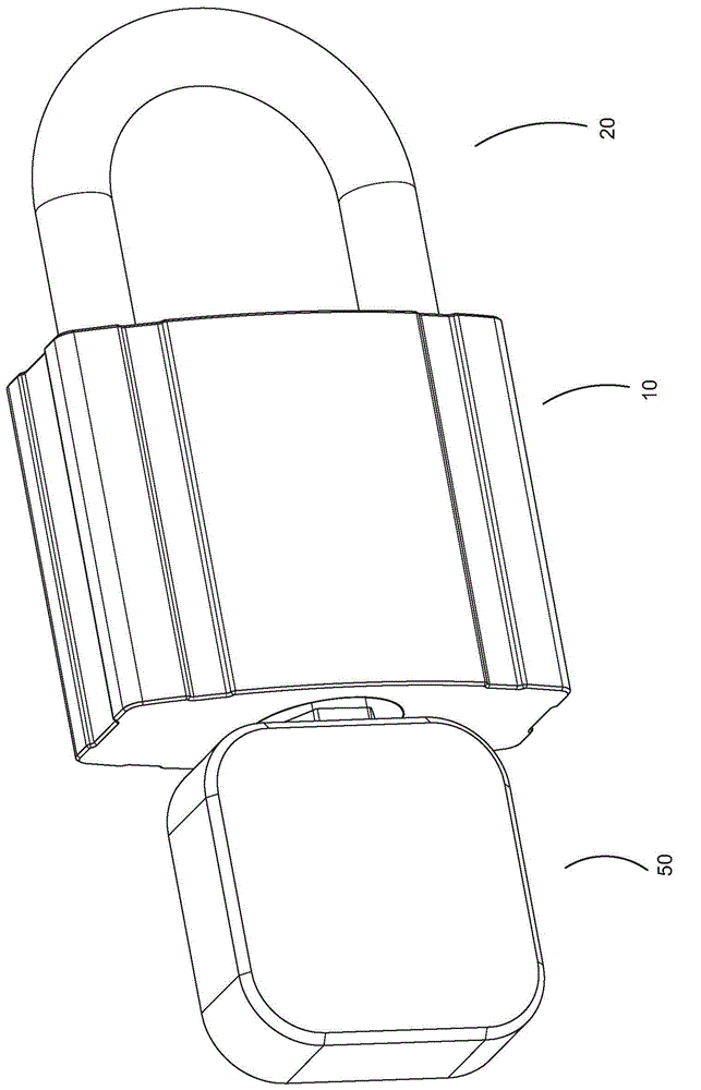
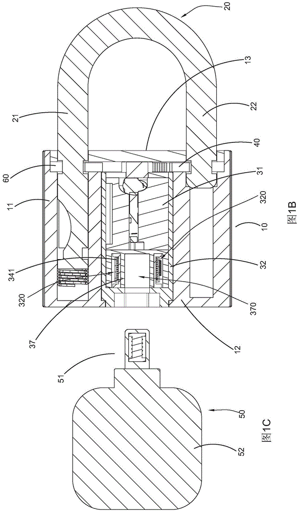
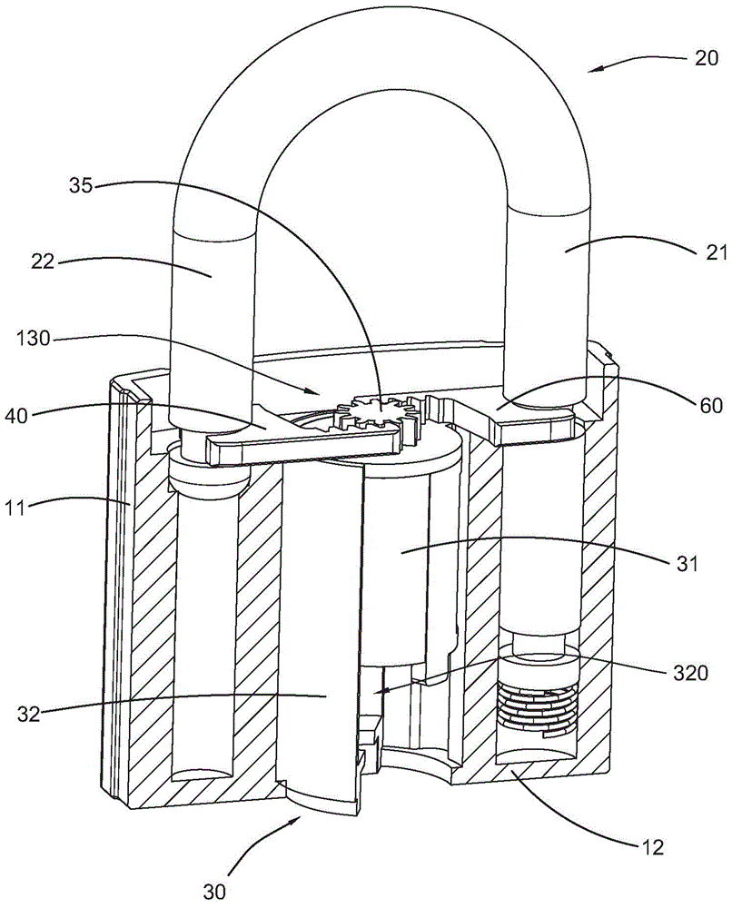
[0046] Refer to Figures 1 to 1 of the accompanying drawings Figure 8B , an electromagnetic lock according to a preferred embodiment of the present invention is illustrated. According to this preferred embodiment, the electromagnetic lock includes a lock body 10, a lock beam 20, a lock cylinder 30 disposed in the lock body 10 and a first locking member 40, wherein the lock beam 20 has a first A leg 21 and a second leg 22, wher...


PUM


Abstract

The invention provides a lock cylinder. The lock cylinder comprises a high-end part, a low-end part and a brake unit, wherein the high-end part of the lock cylinder is provided with a brake chamber extending from top to bottom and a positioning cavity extending horizontally; the positioning cavity is communicated with the brake chamber; the brake chamber of the high-end part of the lock cylinder is provided with a lateral wall and forms a limiting position; the brake unit comprises a brake part arranged inside the positioning cavity of the high-end part of the lock cylinder, a reset part arranged on the brake part and extending from the brake part horizontally, and a limiting bolt; the limiting bolt is arranged on the lateral wall of the brake chamber in a pivoted mode. The invention further provides an unlocking method for an electromagnetic lock.

Description

technical field [0001] The invention relates to an electromagnetic lock, in particular to an electromagnetic lock whose lock body does not need to be provided with an energy storage mechanism such as a battery. Background technique [0002] Existing locks or locksets can be classified into mechanical locks and electronic locks. Traditional mechanical locks are coded by mechanical pins. The unlocker only needs to insert the key into the lock hole of the lock cylinder and turn the lock cylinder through a mechanical force, so that the lock beam of the locked lock can be separated from the lock body and unlocked. The unlocking of this traditional mechanical lock only requires a key with a specific geometric shape, and does not need to confirm the authorization of the unlocker, so that the unlocker only needs to imitate a key with a corresponding shape, or an unlocking tool to open it. Therefore, the safety of this traditional mechanical lock is low, and it is difficult to reali...

Claims


Application Information

Patent Timeline
Patent Type & Authority Applications(China)
IPC IPC(8): E05B47/00E05B15/00
Inventor 鲍成番张秀志禹华夏卞士春石宁缪仁信张秀栈虞成张嘉伟李森洋黄燕玲
Owner SHANGHAI SHENGXIANG SCI & TECH
Why Eureka
Try Eureka