
Open loop mode parallel optical module service life prediction method and apparatus

A technology for life prediction and optical modules, which is applied in the field of optical modules and can solve the problems of unpredictable service cycle life of parallel modules in open-loop mode.

Active Publication Date: 2016-04-06
HISENSE & JONHON OPTICAL ELECTRICAL TECH CO LTD
View PDF3 Cites 4 Cited by
  • Summary
  • Abstract
  • Description
  • Claims
  • Application Information

AI Technical Summary

Problems solved by technology

[0006] The purpose of the present invention is to provide a method and device for predicting the life of parallel modules in open-loop mode to solve the technical problem that the service life of parallel modules in open-loop mode cannot be predicted

Method used

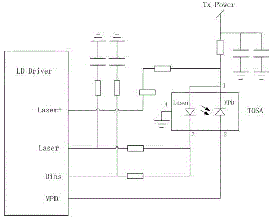
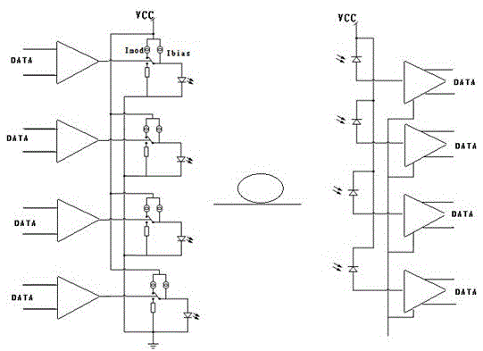
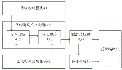

Image

  • Open loop mode parallel optical module service life prediction method and apparatus
  • Open loop mode parallel optical module service life prediction method and apparatus
  • Open loop mode parallel optical module service life prediction method and apparatus

Examples


Embodiment Construction

[0015] In order to make the objectives, technical solutions and advantages of the present invention clearer, the following will combine Attached drawing To further describe the present invention in detail, it is obvious that the described embodiments are only a part of the embodiments of the present invention, rather than all the embodiments. Based on the embodiments of the present invention, all other embodiments obtained by those of ordinary skill in the art without creative work shall fall within the protection scope of the present invention.

[0016] The design idea of ​​the present invention is that: from the perspective of the transmitting module of the optical module alone, the service life of the optical module cannot be monitored and predicted because the open-loop mode defaults to the closed-loop mode of the backlight monitoring diode. Comprehensive consideration, because the response current of the received light intensity indicator signal RSSI of the receiving module...


PUM


Abstract

The invention discloses an open loop mode parallel optical module service life prediction method and apparatus to solve the technical problem that the service life of an open loop mode parallel module cannot be predicted. The method includes the following steps: controlling the power-on sequence of a parallel optical module to enable a transmitting module and a receiving module in the parallel optical module to be powered on at first; after the transmitting module and the receiving module are powered on, controlling the parallel optical module so that the parallel optical module does not transmit data or transmit idle codes; obtaining the response current Irssi (t) of a receiving light intensity indication signal of the receiving module during each power-on process; and determining whether the service life of the parallel optical module runs out on the basis of the response current intensity of the receiving light intensity indication signal. Irssi (t) = R*P (t), R being the response intensity of a receiving module detector. P (t) = S(t)*Ibias (t) and P (t) is the optical power received by the receiving module, Ibias (t) being bias current applied to a laser. Line fiber attenuation is ignored.

Description

technical field [0001] The invention relates to the technical field of optical modules, in particular to a method and device for predicting the lifetime of an open-loop mode parallel optical module. Background technique [0002] In the field of optical fiber digital communication, in order to improve the information transmission bandwidth and enhance the data throughput capability, the optical modules currently used are all parallel optical modules, and the existing parallel optical modules are all open-loop working modes, that is, in order to improve the overall optical module The packaging density and working bandwidth are realized by bare chip COB (Chiponboard, the bare chip is adhered to the interconnection substrate with conductive or non-conductive adhesive, and then wire bonded to achieve its electrical connection) packaging process. The laser uses VCSEL (VerticalCavitySurfaceEmittingLaser, vertical Cavity Surface Emitting Laser) die array, the detector adopts PIN die...

Claims


Application Information

Patent Timeline
Patent Type & Authority Applications(China)
IPC IPC(8): H04B10/073
CPCH04B10/0731
Inventor 谭先友姜瑜斐韩泽
Owner HISENSE & JONHON OPTICAL ELECTRICAL TECH CO LTD
Learn More