c-rnti configuration method and device and system
A configuration method and terminal configuration technology, applied in the field of communication, can solve the problem of high transmission bit error rate, and achieve the effect of reducing the high transmission bit error rate and improving transmission accuracy
- Summary
- Abstract
- Description
- Claims
- Application Information
AI Technical Summary
Problems solved by technology
Method used
Image


Examples
Embodiment 1
[0025] According to an embodiment of the present invention, an embodiment of a C-RNTI configuration method is provided. It should be noted that the steps shown in the flow chart of the accompanying drawings can be executed in a computer system such as a set of computer-executable instructions, and, Although a logical order is shown in the flowcharts, in some cases the steps shown or described may be performed in an order different from that shown or described herein.
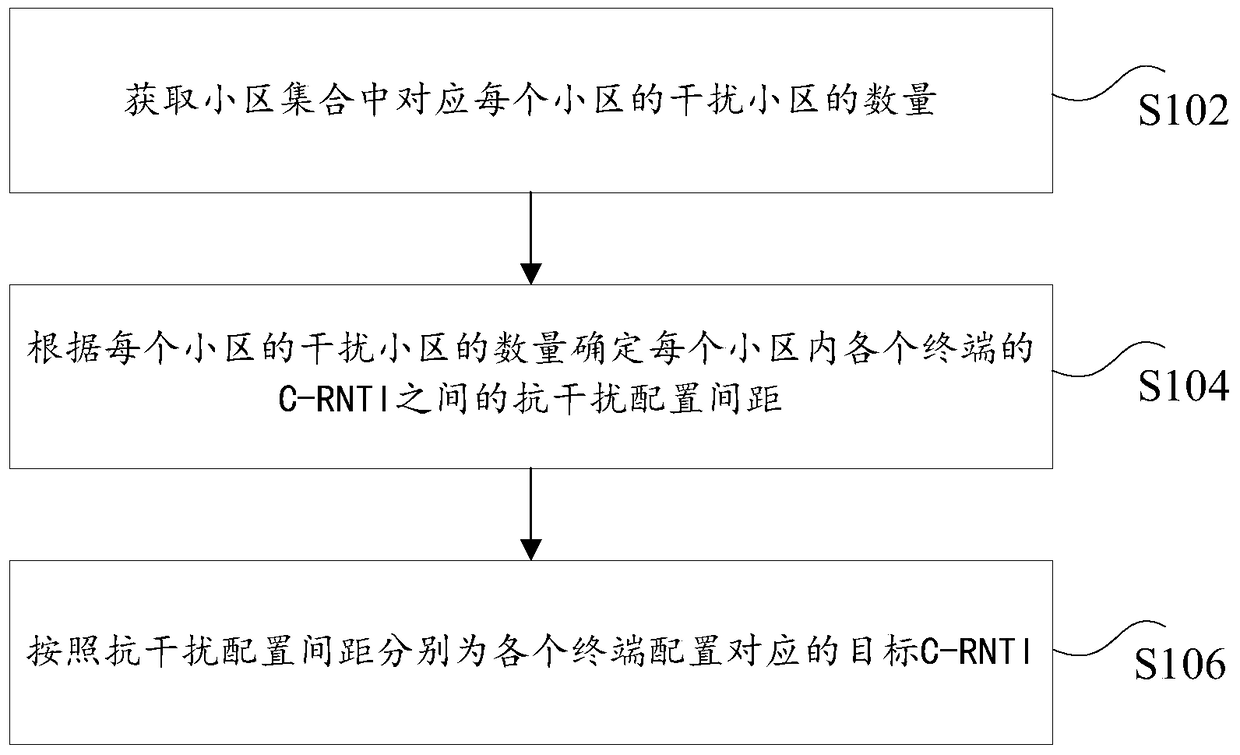
[0026] figure 1 is a C-RNTI configuration method according to an embodiment of the present invention, such as figure 1 As shown, the method includes the following steps:
[0027] S102. Obtain the number of interfering cells corresponding to each cell in the cell set;
[0028] S104. Determine the anti-interference configuration distance between the C-RNTIs of the terminals in each cell according to the number of interfering cells in each cell;
[0029] S106. Configure the corresponding target C-RNTI for each t...
Embodiment 2
[0084] According to an embodiment of the present invention, an embodiment of a C-RNTI configuration device is provided. The above device is located in a core network element, such as Figure 4 As shown, the device includes:
[0085] 1) an acquisition unit 402, configured to acquire the number of interfering cells corresponding to each cell in the cell set;
[0086] 2) A determining unit 404, configured to determine the anti-interference configuration distance between the C-RNTIs of the terminals in each cell according to the number of interfering cells in each cell;
[0087] 3) The configuration unit 406 is configured to respectively configure the corresponding target C-RNTI for each terminal according to the anti-interference configuration interval.
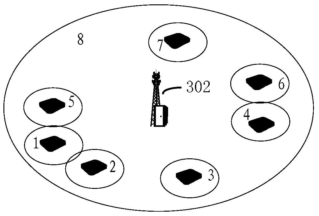
[0088] Optionally, in this embodiment, the above cell temporary user identifier (C-RNTI, Cell Radio NetworkTemporary Identifier) configuration device can be applied to, but not limited to, such as figure 2 In the shown core...
Embodiment 3
[0135] According to an embodiment of the present invention, an embodiment of a C-RNTI configuration system is provided, wherein the system includes:
[0136] 1) A core network element including the above-mentioned C-RNTI configuration device;
[0137] 2) One or more base stations are used to report the interfering cells of the cells corresponding to the base stations.
[0138] Optionally, in this embodiment, the above-mentioned Cell Radio Network Temporary Identifier (C-RNTI, Cell Radio Network Temporary Identifier) configuration system may be applied, but not limited to, to core network elements or network management in the deployment process of the LTE system, Between adjacent cells, or between cells with overlapping coverage areas, when allocating C-RNTI, it is necessary to make the C-RNTI Hamming code distance of different users between the cells as large as possible, so as to reduce the same cell and the same cell as much as possible. Users between adjacent cells have ...
PUM
 Abstract
Description
Claims
Application Information
 - R&D
- Intellectual Property
- Life Sciences
- Materials
- Tech Scout
- Unparalleled Data Quality
- Higher Quality Content
- 60% Fewer Hallucinations
Browse by: Latest US Patents, China's latest patents, Technical Efficacy Thesaurus, Application Domain, Technology Topic, Popular Technical Reports.
© 2025 PatSnap. All rights reserved.Legal|Privacy policy|Modern Slavery Act Transparency Statement|Sitemap|About US| Contact US: help@patsnap.com