Pipe cutting device

A technology of pipe cutting equipment and working platform, which is applied in metal processing and other directions, can solve the problems of increasing program errors, troublesome operation of operators, and prone to malfunction, so as to reduce the probability of program errors, simplify the control program, and simplify the operation. Effect

Inactive Publication Date: 2016-04-13
NINGBO FUSHI AUTOMOBILE COMPONENTS
View PDF7 Cites 3 Cited by
  • Summary
  • Abstract
  • Description
  • Claims
  • Application Information

AI Technical Summary

Problems solved by technology

In the above process, the action of the clamping mechanism generally adopts manual control or program automatic control. When the clamping mechanism is manually controlled, the operator’s operatio...

Method used


Image

  • Pipe cutting device

Examples


Embodiment Construction

[0017] The present invention will be described in further detail below in conjunction with the accompanying drawings and specific embodiments.

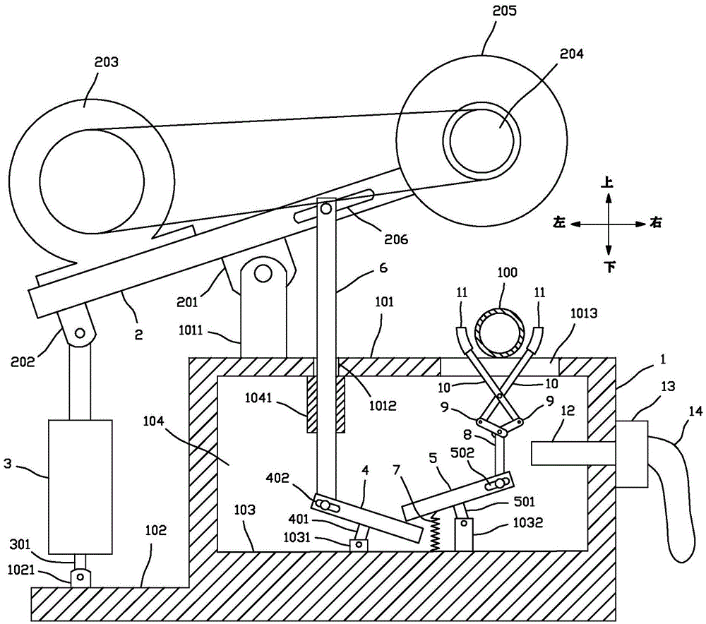
[0018] Depend on figure 1 As shown, the pipe material cutting equipment of the present invention includes a frame 1, and the frame 1 is provided with a first working platform 101 and a second working platform 102, the second working platform 102 is located on one side of the first working platform 101, and the second working platform The platform 102 is lower than the first working platform 101, the first working platform 101 is provided with a first hinged seat 1011, the second working platform 102 is provided with a second hinged seat 1021; the top of the frame 1 is provided with a first rotating plate 2 , the lower surface of the first rotating plate 2 is provided with a first connecting seat 201 and a second connecting seat 202, the first connecting seat 201 is located in the middle of the first rotating plate 2, the first connect...


PUM


Abstract

The invention discloses a pipe cutting device which comprises a cylinder, a first rotating plate, a transmission rod, a second rotating plate, a third rotating plate, a first driving rod, two second driving rods, two third driving rods and two chucks, wherein a cutting wheel is installed on the first rotating plate; when the cylinder drives the first rotating plate to rotate, the cutting wheel moves up and down; when the first rotating plate rotates, the first rotating plate drives the two chucks to close or open through the transmission rod, the second rotating plate, the third rotating plate, the first driving rod, the two second driving rods and the two third driving rods sequentially, so that the two chucks can tightly clamp or loosen a to-be-cut pipe; and a dust collection fan is arranged, so that dust and chippings falling into a cavity can be sucked up. When the device cuts the pipe, a mechanical transmission mode is used for driving a clamping mechanism to clamp the pipe tightly and automatically, and manual control or process control is not required.

Description

technical field [0001] The invention relates to a pipe material cutting device. Background technique [0002] At present, when cutting the pipe, the general operation steps are: 1. Place the pipe at the cutting station; 2. The clamping mechanism clamps and fixes the pipe; 3. The cutting mechanism cuts the pipe; 4. The clamping mechanism Loosen the pipe; 5. Remove the cut pipe. In the above process, the action of the clamping mechanism generally adopts manual control or program automatic control. When the clamping mechanism is manually controlled, the operator’s operation is more troublesome, and when the clamping mechanism is controlled automatically by program, the control process is more cumbersome. Increased the probability of program errors, prone to misoperation. Contents of the invention [0003] The technical problem to be solved by the present invention is to provide a pipe cutting device, which uses mechanical transmission to drive the clamping mechanism to auto...

Claims


Application Information

Patent Timeline
IPC IPC(8): B26D7/02B26D1/157B26D7/18
CPCB26D7/02B26D1/157B26D7/18B26D7/1863
Inventor 陈荣发
Owner NINGBO FUSHI AUTOMOBILE COMPONENTS
Why Eureka
Try Eureka