Metal separator

A metal separator and separator technology, applied in grain processing and other directions, can solve the problems of increasing labor intensity of workers, waste of powder materials, etc., and achieve the effect of saving labor costs and reducing labor intensity

Inactive Publication Date: 2016-04-13
合肥光裕机械有限责任公司
View PDF0 Cites 7 Cited by
  • Summary
  • Abstract
  • Description
  • Claims
  • Application Information

AI Technical Summary

Problems solved by technology

[0002] When processing air-conditioning injection molding, it is necessary to carry out metal separation operations on the injection molding crushed materials in the crushing room. When passing through the metal separator, one bag at

Method used


Image

  • Metal separator

Examples


Example Embodiment

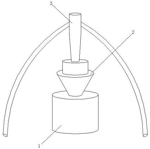
[0007] See figure 1 , This specific embodiment adopts the following technical solutions: it includes a separator 1, a hopper 2, a hopper 2 is arranged above the separator 1, and the hopper 2 is connected to the lower outlet of the suction bin 3, and the suction port of the suction bin 3 Connect with the outlet of the crusher. When working, the injection powder crushed by the pulverizer will be discharged through the outlet of the pulverizer, and then sucked in through the suction port of the hopper, and then sent to the hopper of the separator through the lower outlet of the hopper, and finally passed through the separator. The metal is separated, and the separator can be smashed and separated during the entire working process, which realizes automatic cycle work, saves personnel costs, reduces labor intensity of personnel, and avoids waste of powder.


PUM


Abstract

The invention discloses a metal separator and relates to the technical field of air conditioner production. The metal separator comprises a separator body and a material hopper. The material hopper is arranged above the separator body and connected with a lower outlet of a material suction bin. A material suction opening of the material suction bin is connected with a pulverizer outlet. According to the metal separator, the position of the material suction bin is raised currently, and the separator material hopper is fixed under the material suction bin. In this way, smashing and separation can be conducted simultaneously, so that automatic cycle operation is achieved, the personnel cost is reduced, and personnel labor intensity is relieved.

Description

Technical field [0001] The invention relates to the technical field of air-conditioning production, in particular to a metal separator. Background technique [0002] When processing air-conditioning injection molding, it is necessary to carry out the metal separation operation of the injection crushed material in the crushing room. When passing the metal separator, bag by bag must be poured into the separator hopper for separation, which increases the labor intensity of the workers. Because every time the material is poured, it will be sprinkled on the ground and cause powder waste. Summary of the invention [0003] The purpose of the present invention is to provide a metal separator with automatic cycle work. [0004] In order to solve the problems in the background technology, the present invention adopts the following technical solutions: it includes a separator and a hopper, a hopper is arranged above the separator, and the hopper is connected to the lower outlet of the suction...

Claims


Application Information

Patent Timeline
IPC IPC(8): B29B13/10B02C21/00
Inventor 岳朝风
Owner 合肥光裕机械有限责任公司
Why Eureka
Try Eureka