Method and system for performing a logical loopback test

a loopback test and loopback technology, applied in the field of logical layer testing in the telecommunications network, can solve the problems of not being able to determine what is occurring at the logical layer, physical layer testing cannot determine where the problem lies, and the difficulty of effectively and efficiently monitoring and managing the networks supporting the providers' customers, etc., to achieve the effect of reducing both the equipment and personnel costs associated

Inactive Publication Date: 2007-03-06
AT&T INTPROP I L P
View PDF5 Cites 9 Cited by
  • Summary
  • Abstract
  • Description
  • Claims
  • Application Information

AI Technical Summary

Benefits of technology

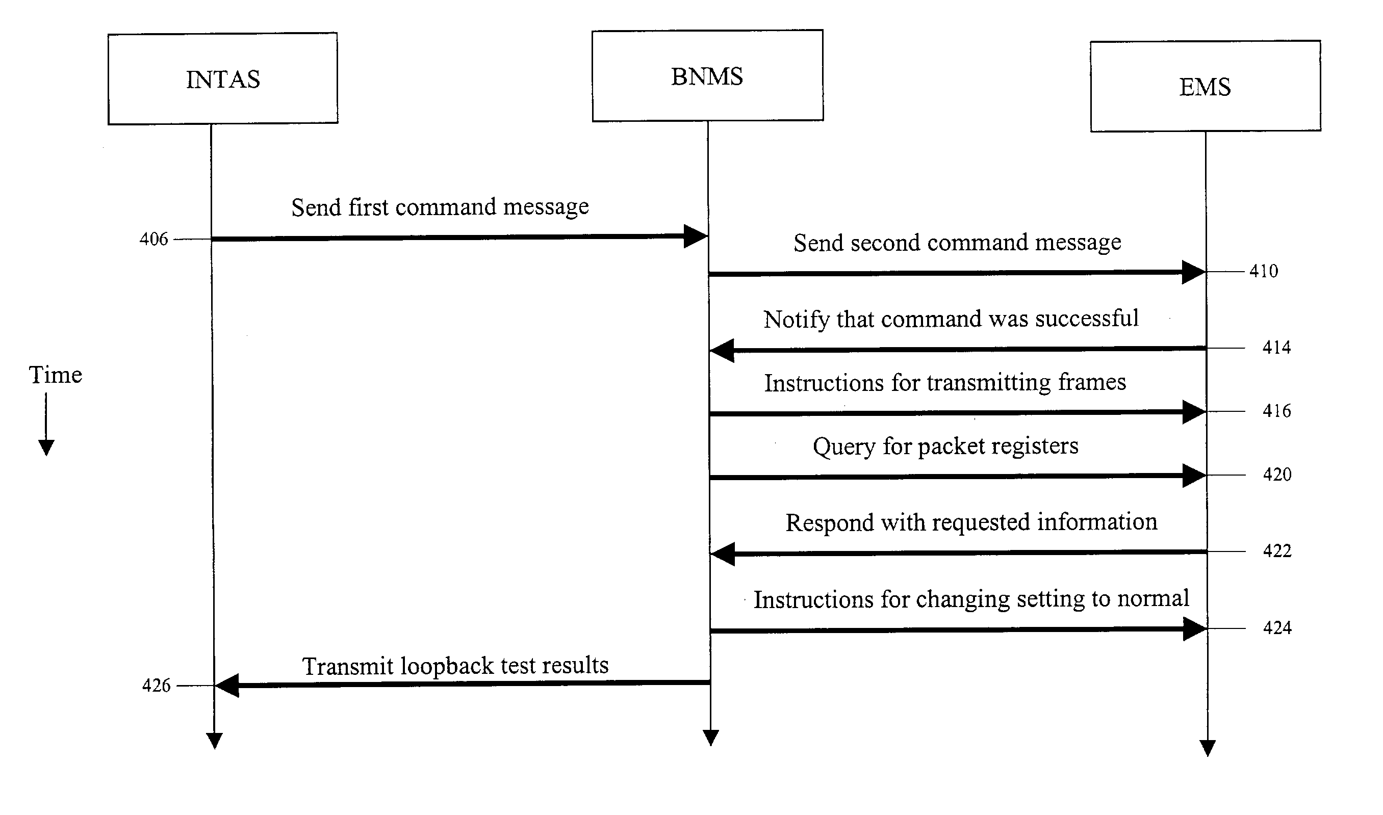
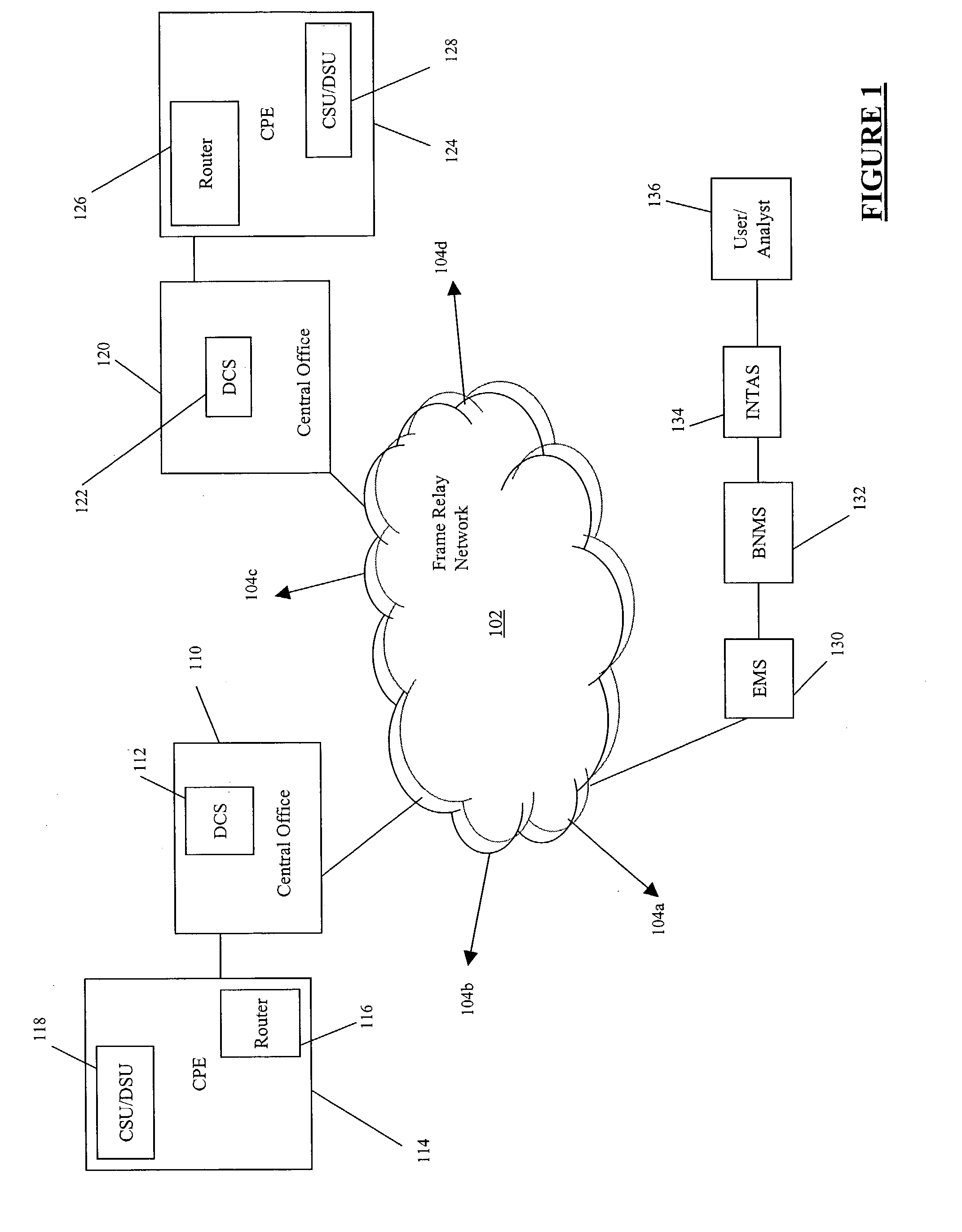
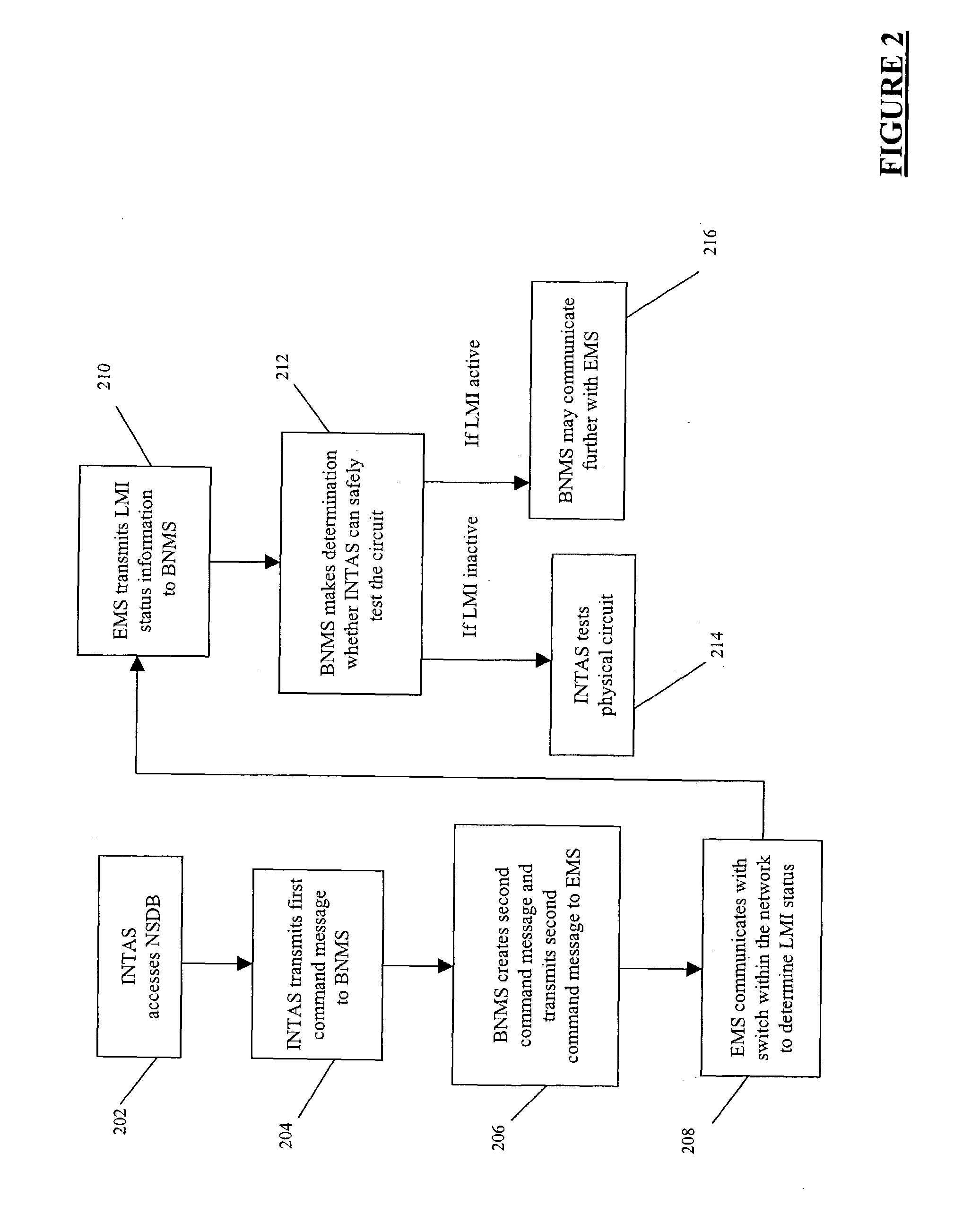
[0010]The present invention allows for remote testing for logical layer information by placing an INTAS, a BNMS, and an EMS in communication in series. The present invention allows users or analysts to obtain logical layer information remotely using a physical layer test system, whereas previously obtaining logical layer information required human personnel physically testing each individual circuit using a logical test box connected to the circuit itself or a DCS providing physical access to multiple circuits. Methods and systems of the present invention allow for the use of a single logical test box connected to the frame relay and / or ATM network in each LATA. Accordingly, for example, rather than needing 25–30 boxes for the Atlanta LATA, only a single logical test box is needed, greatly reducing both the equipment and personnel costs associated with obtaining logical layer information.

Problems solved by technology

As the number of customer and network installations has increased, so has the difficulty of effectively and efficiently monitoring and managing the networks supporting the providers' customers.
However, in creating and testing a loop between points A and B, there is no way to determine what is occurring at the logical layer.
Thus, if the network problem is in the logical portion of the frame relay or ATM network, physical layer testing cannot determine where the problem lies.
Presently, no cost effective remote logical layer testing solutions exist.

Method used


Image

  • Method and system for performing a logical loopback test
  • Method and system for performing a logical loopback test
  • Method and system for performing a logical loopback test

Examples


Embodiment Construction

[0020]The following detailed description utilizes a number of acronyms which are generally well known in the art. While definitions are typically provided with the first instance of each acronym, for convenience, Table 1 below provides a list of the acronyms and their respective definitions.

[0021]

TABLE 1ACRONYMDEFINITIONADSLAsymmetric Digital Subscriber LineATMAsynchronous Transfer ModeBNMSBroadband Network Management SystemCACConnection Admission ControlCIRCommitted Information RateCLICommand Line InterfaceCMIPCommon Management Information ProtocolCPECustomer Premises EquipmentCSU / DSUChannel Service Unit / Data Service UnitDCSDigital Cross-ConnectDLCIData Link Connection IdentifierDSLAMDigital Subscriber Line Access MultiplexerEMSElement Management SystemFRADFrame Relay Access DeviceGUIGraphical User InterfaceHDSLHigh-speed Digital Subscriber LineHLUHDSL Line UnitHRUHDSL Remote UnitINTASIntegrated Testing and Analysis SystemIPInternet ProtocolLATALocal Access Transport AreaLMILink Ma...


PUM


Abstract

Systems and methods for obtaining logical layer information in a frame relay and/or asynchronous transfer mode (ATM) network are described. In an exemplary embodiment, a physical layer test system, such as an integrated testing and analysis system, communicates with a broadband network management system, which in turn communicates with an element management system for a frame relay and/or ATM network.

Description

CROSS-REFERENCE TO RELATED APPLICATIONS[0001]This application relates to Ser. No. 10 / 318,540, filed simultaneously, entitled “Method and System for Retrieving Link Management Interface Status for a Logical Port,” which is incorporated herein by reference. This application relates to Ser. No. 10 / 318,932, filed simultaneously, entitled “Method and System for Obtaining a Network Map,” which is incorporated herein by reference. This application relates Ser. No. 10 / 318,467, filed simultaneously, entitled “Method and System for Obtaining a Permanent Virtual Circuit Map,” which is incorporated herein by reference.FIELD OF THE INVENTION[0002]The present invention generally relates to logical layer testing in a telecommunications network. The present invention more particularly relates to methods and systems for obtaining logical layer information using a remote physical layer testing device.BACKGROUND OF THE INVENTION[0003]According to Vertical Systems Group, customer installations of carri...

Claims


Application Information

Patent Timeline
Patent Type & Authority Patents(United States)
IPC IPC(8): H04J1/16G01R31/08H04L12/24H04L12/56
CPCH04L41/32H04L41/0213H04L2012/5628H04L41/06
Inventor TAYLOR, WILLIAM SCOTTMASSENGILL, DAVID E.
Owner AT&T INTPROP I L P
Why Eureka
Try Eureka