Breaking hammer with shearing device

A technology of shearing device and breaking hammer, applied in construction maintenance, earth mover/shovel, construction, etc., can solve problems such as troublesome operation of workers, troublesome excavator bucket shoveling garbage, failure to cut off in time, etc.

Active Publication Date: 2016-04-13
XUZHOU DONGYA ELECTRICAL APPLIANCE
View PDF6 Cites 4 Cited by
  • Summary
  • Abstract
  • Description
  • Claims
  • Application Information

AI Technical Summary

Problems solved by technology

In particular, some foundation steel bars on the ground are still quite thick. Generally, the manual cutters are cut continuously, and they have to be handled by other personnel and tools. The work of the breaker is often interrupted and then resumed.
There are often many small and small steel bars in the cement body, and they have to be cut manually and then continue to be impacted. This affects the construction progress and brings troubles to the workers.
In the process of demolishing old houses, there are quite a lot of steel bars exposed on the frame of the building and the cement board on the floor, which are often not cut off in time, which seriously affects the construction of the breaker, and the steel bars are messy piled up in the construction waste, which brings a lot of trouble to the excavator bucket. A lot of trouble, affecting work efficiency

Method used


Image

  • Breaking hammer with shearing device
  • Breaking hammer with shearing device

Examples


Embodiment

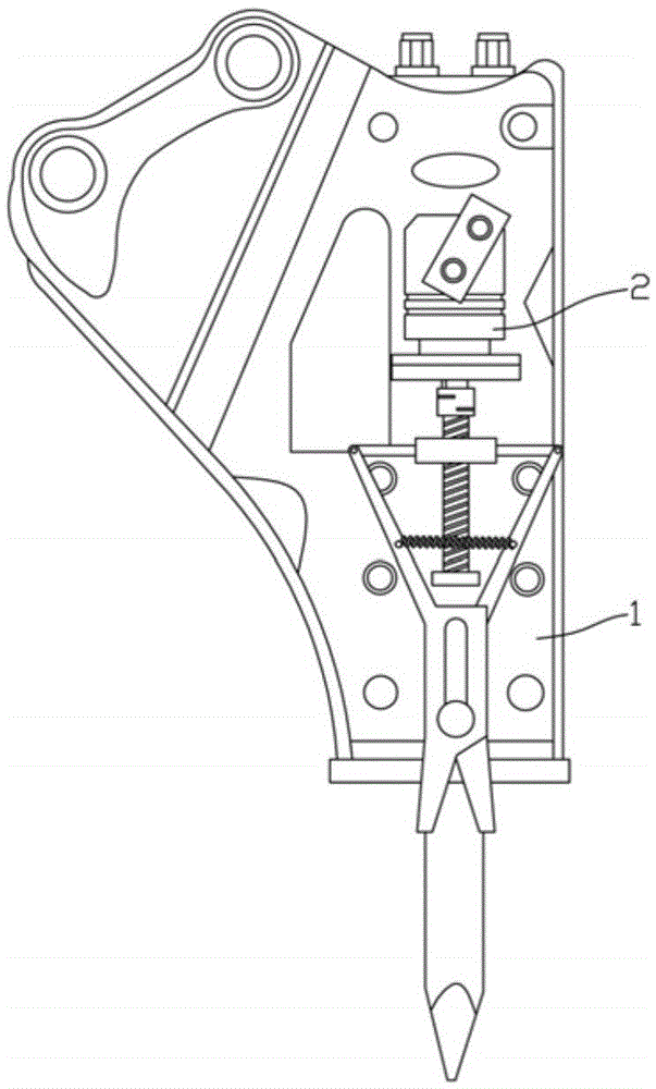
[0014] Example: see figure 1 , 2 As shown, a breaker with a shearing device includes a breaker 1, and a shearing mechanism 2 is fixedly connected to the breaker 1;

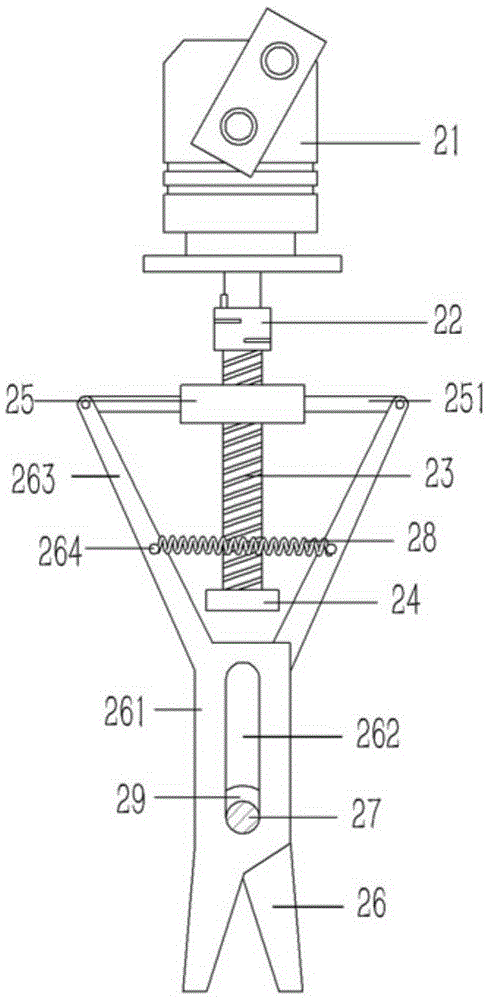
[0015] The shearing mechanism 2 includes a hydraulic motor 21 fixed on the side wall of the breaker 1. The rotating shaft of the hydraulic motor 21 is connected with the upper end of a vertical screw 23 through a coupling 22, and the lower end of the screw 23 is hinged on the base 24, the base 24 is fixed on the side wall of the breaker 1, and the lower side of the base 24 is provided with a shear knife, which is composed of two staggered and symmetrical blades 26, and the blade 26 is formed into a rectangular piece extending upward. body 261, a vertical guide groove 262 is formed on the rectangular piece body 261, the guide grooves 262 of the two blades 26 overlap together, and a guide column 27 is inserted in the guide groove 262, and the guide column 27 is fixed on the side wall of the breaker 1 Above, the up...


PUM


Abstract

Disclosed is a breaking hammer with a shearing device. A shearing mechanism of the breaking hammer comprises a hydraulic motor, wherein the hydraulic motor is fixed to the side wall of a breaking hammer body. A rotating shaft of the hydraulic motor and the upper end of a vertical lead screw are connected together through a coupler, and the lower end of the lead screw is hinged to a base. The base is fixed to the side wall of the breaking hammer body. A shearing knife is arranged on the lower side of the base, and comprises two staggered and symmetrical blades. Rectangular piece bodies which extend upwards are formed on the blades, vertical guide grooves are formed in the rectangular piece bodies, and the guide grooves of the two blades overlap together. A guide column is inserted into the guide grooves in a connected mode, and fixed to the side wall of the breaking hammer body. Inclined connecting rods are formed at the upper ends of the rectangular piece bodies of the blades. A rectangular sliding block is connected to the lead screw in a screwed mode, and abuts against the side wall of the breaking hammer body, supporting rods are formed on the two sides of the sliding block, and the top ends of the connecting rods on the blades are hinged to the supporting rods. The breaking hammer is provided with the shearing mechanism, and the shearing mechanism can be hydraulically driven to shear off rebars in the construction process.

Description

Technical field: [0001] The invention relates to the technical field of breaking hammers, in particular to a breaking hammer with a shearing device. Background technique: [0002] Existing breaking hammer is mainly used for impacting rock, cement pavement, cement pouring foundation, old building demolition etc., has unique effect. When dismantling the cement pouring frame of the old building, especially the ground foundation, after impacting and breaking the cement block, the steel bars are exposed and cannot be cut off. In particular, some ground foundation steel bars are still quite thick, and the general manual cutters are all cut continuously, and it has to be handled by other personnel and tools, and the work of the breaker is often interrupted and then continued. There are often many small steel bars in the cement body, and they have to be manually cut and then continue to impact, which affects the construction progress and brings trouble to the workers. In the proce...

Claims


Application Information

Patent Timeline
Patent Type & Authority Applications(China)
IPC IPC(8): E02F5/30E04G23/08
CPCE02F5/305E04G23/082
Inventor 杜福安
Owner XUZHOU DONGYA ELECTRICAL APPLIANCE
Why Eureka
Try Eureka