Device for cutting coils

A technology of coil cutting and slot placement, applied in metal processing and other directions, can solve the problems of excessive manual manual operation, increased labor intensity, low degree of automation, etc., and achieves the effect of easy use, saving manpower and financial resources, and simple device structure.

Inactive Publication Date: 2019-01-25
广州俊天科技有限公司
View PDF0 Cites 0 Cited by
  • Summary
  • Abstract
  • Description
  • Claims
  • Application Information

AI Technical Summary

Problems solved by technology

[0002] In the processing and production of PVC floor coils, trimming operations are often performed, while the traditional coil trimming device has a low degree of automation and requires too much manual operation, which greatly increases labor intensity and reduces Work efficiency has been compromised, but there are major drawbacks that need to be improved

Method used


Image

  • Device for cutting coils
  • Device for cutting coils
  • Device for cutting coils

Examples


Embodiment Construction

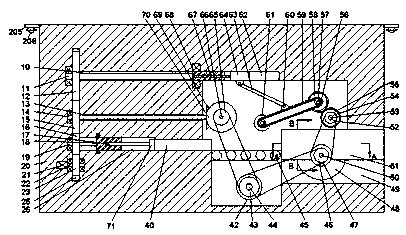
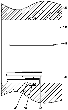
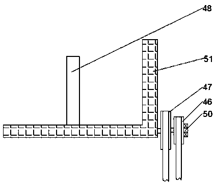
[0019] Such as Figure 1-3 As shown, a coil cutting device of the present invention includes a box casing 20, a motor 21 is arranged inside the box casing 20, and a first motor 21 located in the box casing 20 is arranged on the right side of the Settling groove 25, the first settling groove 25 is provided with the first revolving pin shaft 22 that is rotatably matched with the bottom of the left and right end walls, and the extension of the left end of the first revolving pin shaft 22 is power-connected with the motor 21, and the first revolving pin shaft 22 is power-connected with the motor 21. The left end of the first revolving pin shaft 22 of a settling groove 25 is fixedly connected with the first toothed wheel 23, and the right side of the first settling groove 25 is provided with a communicating first through cavity 26, and the first through cavity 26 and the first placement groove 25 are rotationally connected with a second pivot shaft 19, and the second pivot shaft 19...


PUM


Abstract

The invention relates to a device for cutting coils. The device comprises a box shell, a motor is arranged inside the box shell, a first containing groove located in the box shell is formed in the right side of the motor and provided with a first rotating pin shaft rotatably matched with the bottoms of the left and right end walls, the extending part of the left end of the first rotating pin shaftis in power connection with the motor, a first tooth-shaped wheel is fixedly and cooperatively connected to the left end of the first rotating pin shaft of the first containing groove, a first through cavity is communicated with the right side of the first containing groove, a second rotating pin shaft is rotatably and cooperatively connected between the first through cavity and the first containing groove, and the second rotating pin shaft of the first containing groove is fixedly and cooperatively connected with a second tooth-shaped wheel cooperatively connected with the first tooth-shapedwheel.

Description

technical field [0001] The invention relates to the technical field of PVC floor coil processing, in particular to a coil cutting device. Background technique [0002] In the processing and production of PVC floor coils, trimming operations are often performed, while the traditional coil trimming device has a low degree of automation and requires too much manual operation, which greatly increases labor intensity and reduces Work efficiency has been reduced, and there are relatively large drawbacks, which need to be improved. Contents of the invention [0003] Aiming at the deficiencies of the above technologies, the present invention proposes a coil cutting device. [0004] A coil cutting device according to the present invention comprises a box casing, a motor is arranged inside the box casing, and a first placement groove located in the box casing is arranged on the right side of the motor, and the first placement groove There is a first rotating pin shaft that is rota...

Claims


Application Information

Patent Timeline
Patent Type & Authority Applications(China)
IPC IPC(8): B26D1/15B26D7/06
CPCB26D1/15B26D7/06B26D7/0608
Inventor 龚土婷
Owner 广州俊天科技有限公司
Why Eureka
Try Eureka