
Open-type drying furnace for automobile parts

An auto parts, open technology, applied in drying, dryer, progressive dryer and other directions, can solve the problem of slow opening of isolation door, lower temperature of drying room, affecting drying, etc., to achieve high utilization rate , the effect of speeding up drying and improving production efficiency

Inactive Publication Date: 2016-04-13
东莞丰裕电机有限公司
View PDF7 Cites 11 Cited by
  • Summary
  • Abstract
  • Description
  • Claims
  • Application Information

AI Technical Summary

Problems solved by technology

However, in the existing drying furnaces, in order to maintain a higher temperature in the drying chamber and prevent rapid heat loss, isolation doors are generally installed at the entrance and exit, and the isolation door is used to isolate the drying chamber from the outside world. In the drying room, the isolation door is controlled to open, and the isolation door is closed during baking, so as to realize the constant temperature of the drying room; however, the opening of this isolation door is slow, and the workpiece usually needs to wait for a certain period of time before it reaches the isolation door. In and out, the heat will be quickly lost from the inlet and outlet during this period, which will reduce the temperature of the drying chamber and affect the drying; therefore, the existing drying furnace not only needs to control the multiple start and stop of the conveyor belt, but the control is complicated , and when the isolation door is opened, the heat loss in the drying chamber is relatively serious, which makes the energy consumption of the drying furnace high, the drying speed is slow, and the production efficiency is low

Method used


Image

  • Open-type drying furnace for automobile parts
  • Open-type drying furnace for automobile parts
  • Open-type drying furnace for automobile parts

Examples


Embodiment Construction

[0019] In order to describe the technical content, structural features, and achieved effects of the present invention in detail, the following will be described in detail in conjunction with the embodiments and accompanying drawings.

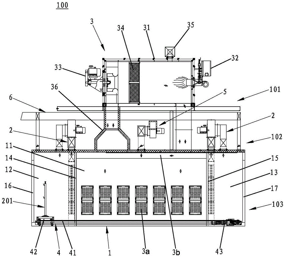
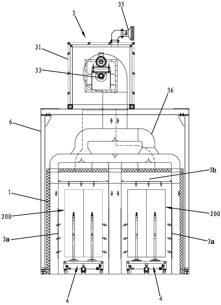
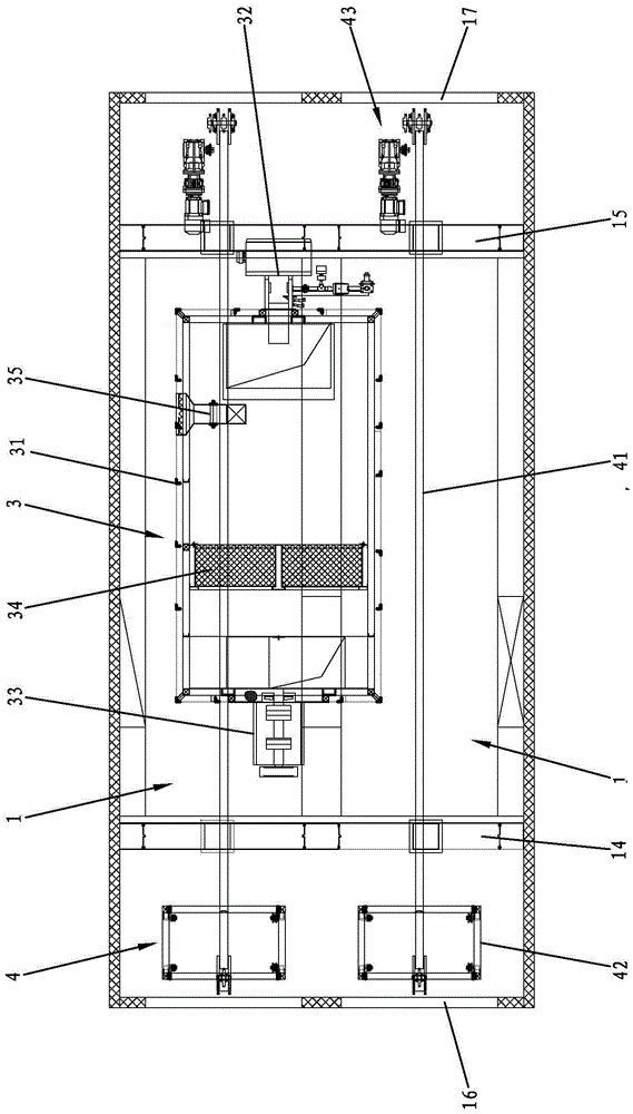
[0020] Such as figure 1 As shown, the open drying furnace 100 for auto parts of the present invention includes a furnace body main body 1, two air curtain machines 2, a hot air circulation system 3, a conveying chain 4 and an exhaust fan 5; The steel structure platform 6 makes the open drying furnace 100 for auto parts divided into an upper layer 101, a middle layer 102 and a lower layer 103, the furnace main body 1 is located in the lower layer 103, the two air curtain machines 2 and the Exhaust gas blower 5 is positioned at described middle layer 102, and described hot air circulation system 3 is positioned at upper layer 101; By being divided into three layers, make the drying oven of the present application utilize the space of upper layer 1...


PUM


Abstract

The invention discloses an open-type drying furnace for automobile parts. The open-type drying furnace comprises a main body of a furnace body, an air curtain machine, a hot air circulating system and a conveying chain, wherein the main body of the furnace body is provided with a drying region as well as a levelling region and a cooling region which are respectively communicated with the drying region, and the levelling region and the cooling region are respectively communicated with the outside in an open way; the air curtain machine is respectively arranged between the levelling region and the drying region and between the drying region and the cooling region so as to spray an air curtain to partition the two adjacent regions; the hot air circulating system is arranged above the main body of the furnace body, and a hot air inlet and a hot air outlet are communicated with the drying region; and the conveying chain is arranged at the inner bottom of the main body of the furnace body and is used for conveying automobile parts input from an inlet of the furnace body to an outlet of the furnace body through the levelling region, the drying region and the cooling region. The open-type drying furnace for automobile parts has the advantages of high drying speed, high production efficiency and energy saving.

Description

technical field [0001] The invention relates to a drying device, in particular to an open drying furnace for auto parts. Background technique [0002] Spraying treatment is generally required on the surface of industrial products, and the spraying process has been widely used in products in industries such as automobiles, home appliances, plastics and furniture. [0003] In order to make the spray paint on the surface of the product adhere more firmly, the product needs to be dried after spraying. For the drying process, the traditional oven is currently used. After spraying, the product is transferred to the heated drying chamber by the conveyor belt. After a period of baking, it is cooled in the cooling chamber and finally sent out by the conveyor belt. However, in the existing drying furnaces, in order to maintain a higher temperature in the drying chamber and prevent rapid heat loss, isolation doors are generally installed at the entrance and exit, and the isolation doo...

Claims


Application Information

Patent Timeline
Patent Type & Authority Applications(China)
IPC IPC(8): F26B15/04F26B21/00
CPCF26B15/04F26B21/00
Inventor 郑锡辉
Owner 东莞丰裕电机有限公司
Learn More