
Propeller dynamic balance tester

A dynamic balance tester and balance test technology, applied in static/dynamic balance test, machine/structural component test, instrument, etc., can solve the problems of inability to test self-locking propeller dynamic balance performance, single test function, etc., to achieve The effect of testing is convenient and fast, expanding the scope of application, and simple structure

Active Publication Date: 2016-04-13
SHENZHEN YOUKESHU TECH CO LTD
View PDF6 Cites 10 Cited by
  • Summary
  • Abstract
  • Description
  • Claims
  • Application Information

AI Technical Summary

Problems solved by technology

[0004] For this reason, the present invention aims to solve the technical problem that the existing propeller dynamic balance tester has a single test function, can only measure non-locking propellers, and cannot test the dynamic balance performance of self-locking propellers, and proposes a propeller dynamic balance tester that can measure self-locking propellers balance tester

Method used


Image

  • Propeller dynamic balance tester
  • Propeller dynamic balance tester
  • Propeller dynamic balance tester

Examples


Embodiment 1

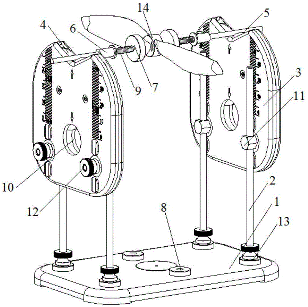
[0035] Such as figure 1 As shown, the present invention provides a propeller balance tester, which includes,

[0036] The base 1, preferably, the base is rectangular.

[0037] The support rod 2 is detachably arranged on the four corners of the base 1 by fixing screws 13, and the support rod 2 is installed on one end of the base 1 to be provided with threads, and the base 1 is provided with two rows of screw holes 8, Two rows of screw holes 8 are respectively arranged along the long sides of the rectangular base. In this embodiment, each row of screw holes 8 includes three screw holes, and the two rows of screw holes are arranged symmetrically along the center line of the base. Matched to fix the support rod 2, the two rows of screw holes 8 can be adapted to different types of propellers to be tested.

[0038] The fixed bracket 3 is a hollow structure with an upper end opening. In this embodiment, the opening is arranged directly above the fixed bracket 3, and the opening is...

Embodiment 2

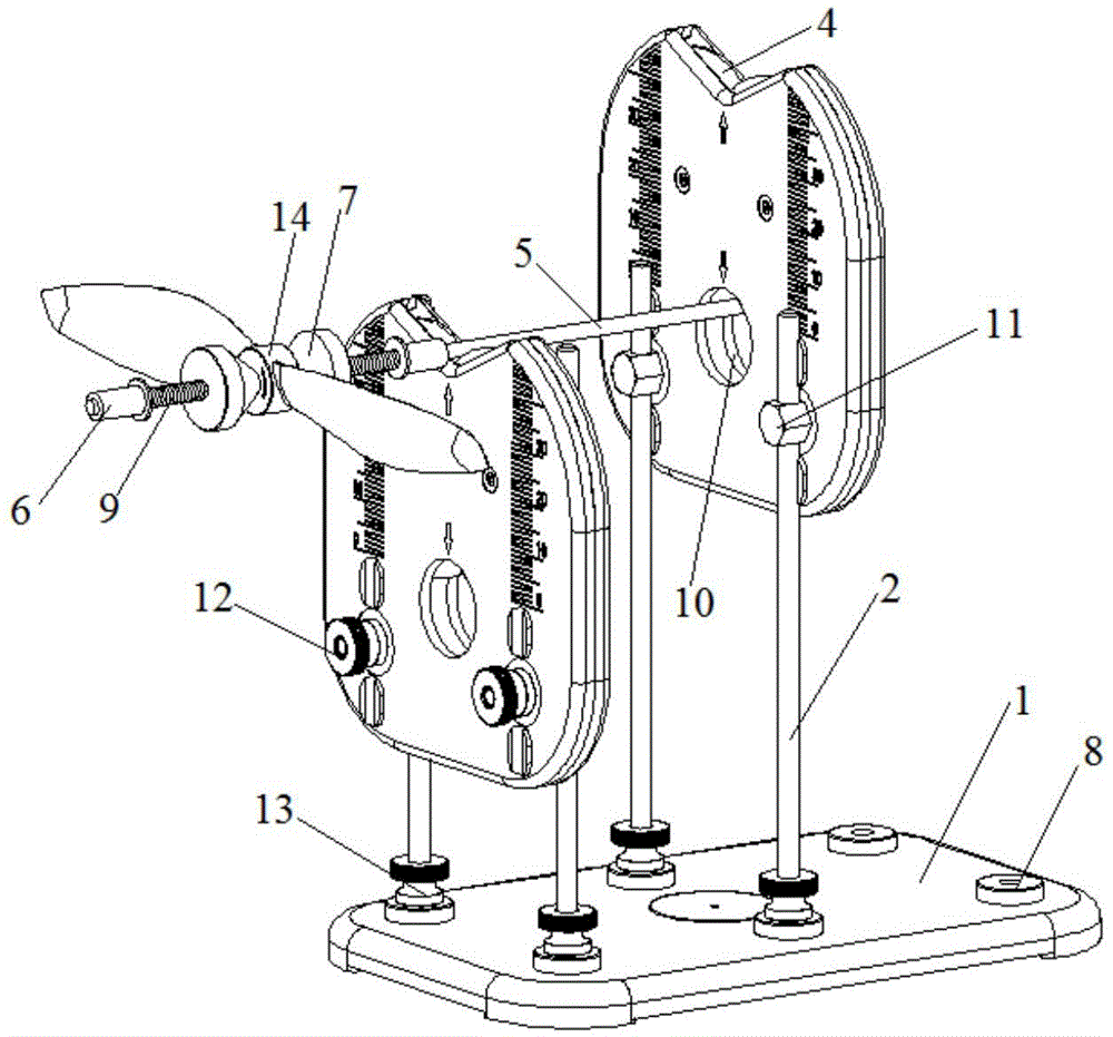
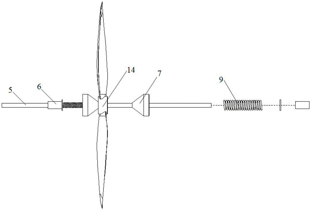
[0046] Such as Figure 4-5 As shown, the structure of the propeller tester described in this embodiment is basically the same as that of Embodiment 1, the difference is that the propeller tester in this embodiment can test the self-locking type with a closed nut structure at one end of the propeller hub 14. Propeller, therefore, the propeller tester of the present embodiment comprises:

[0047] base1;

[0048] The support rod 2 is detachably arranged on the base 1;

[0049] The fixed bracket 3 is a hollow structure with an upper end open, detachably connected to the support rod 2 and the position of the fixed bracket 3 on the support rod 2 is adjustable, and the fixed bracket 3 is two and opposite Setting, the two fixed brackets 3 are respectively provided with a through hole 10 along the part directly below the opening;

[0050] The balance test assembly 4 is arranged inside the hollow structure of each of the fixed brackets 3, and the working part of the balance test asse...


PUM


Abstract

The invention discloses a propeller dynamic balance tester. The propeller dynamic balance tester comprises a base, supporting rods which are detachably arranged on the base, fixing brackets which are detachably connected onto the supporting rods, balance test assemblies which are arranged in the hollow structures of each fixing bracket, a balance connection mechanism which is erected on the balance test assemblies and is used for fixing a propeller to be tested; the positions of the fixing brackets on the supporting rods are adjustable; and one end of the balance connection mechanism is provided with a diameter-variable ring; and in a test, the propeller hub hollow part of a self-locking type propeller sleeves the diameter-variable ring. With the propeller dynamic balance tester adopted, the self-locking type propeller can be tested. The propeller dynamic balance tester has the advantages of simple structure and low cost.

Description

technical field [0001] The invention relates to a balance test device, in particular to a propeller dynamic balance tester. Background technique [0002] Propeller refers to a device that converts the rotational power of the engine into propulsion by rotating the blades in the air or water. There may be two or more blades connected to the hub, and the rear side of the blades is a helical surface or similar to a helical surface. A marine propeller. There are many types of propellers, and they are widely used, such as propellers for airplanes and ships. Due to the casting and processing errors of the new propeller, such as the error of the blade thickness, width, angle between the blades, and the blade back rake angle; The chemical properties and mechanical properties of the blades are not uniform, resulting in unbalanced chemical corrosion, cavitation, wear, etc. of the blades, blade damage repair, improper grinding after edge cutting, all of which will cause the propeller ...

Claims


Application Information

Patent Timeline
Patent Type & Authority Applications(China)
IPC IPC(8): G01M1/14
CPCG01M1/14
Inventor 朱红先吴立国
Owner SHENZHEN YOUKESHU TECH CO LTD
Learn More