Contact assembly for electromechanical switching device, and electromechanical switching device

A technology of contact device and electromechanical switch, which is applied in the direction of electric switch, electromagnetic relay, detailed information of electromagnetic relay, etc., can solve the problem of increasing assembly cost and achieve the effect of reliable positioning

Active Publication Date: 2016-04-13
SIEMENS AG
View PDF3 Cites 3 Cited by
  • Summary
  • Abstract
  • Description
  • Claims
  • Application Information

AI Technical Summary

Problems solved by technology

[0006] The contact devices with spring bows known from the prior art have the disadvantage that additio

Method used


Image

  • Contact assembly for electromechanical switching device, and electromechanical switching device
  • Contact assembly for electromechanical switching device, and electromechanical switching device
  • Contact assembly for electromechanical switching device, and electromechanical switching device

Examples


Embodiment Construction

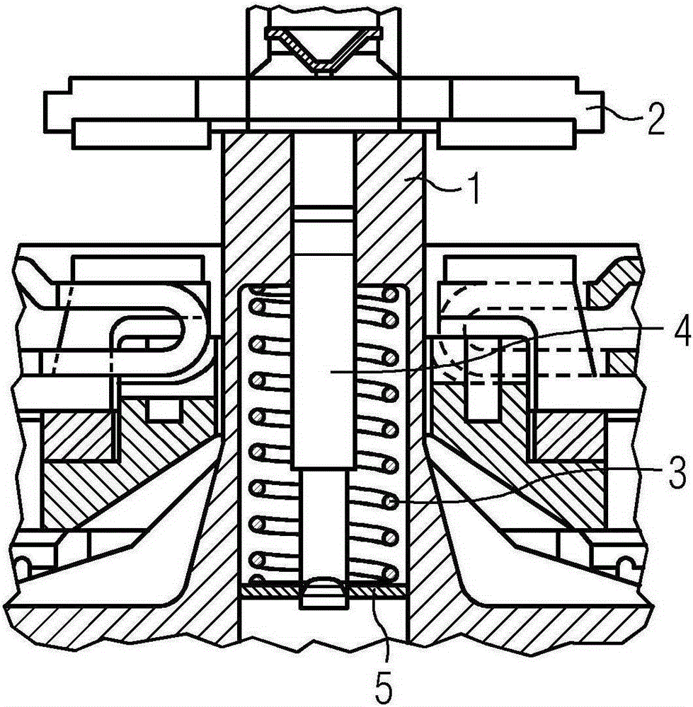
[0029] FIG. 1 shows a contact device known from the prior art with a contact carrier 1 which guides a movable switching part 2 , wherein the movable switching part 2 is loaded on one side by a contact spring 3 . On the opposite side, that is to say on the side of the movable switching part 2 , the spring bow 4 is introduced into the contact carrier 1 . In order to support the contact spring 3 , a steel plate 5 is fitted under the contact spring 3 through a rotational movement.

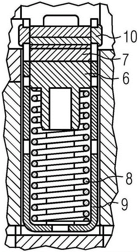
[0030] A further contact arrangement known from the prior art is shown in FIG. 2 . FIG. 2 shows a contact device with a contact carrier 6 which guides a movable switching part 7 , wherein the movable switching part 7 is supported on a contact spring 8 which is inserted from below into the contact carrier 6. Likewise, the spring bow 9 is pushed into the contact carrier 6 from below. The movable switching element 7 is located from above between the two legs of the spring bow 9 . By pressing one end ...


PUM


Abstract

The invention relates to a contact assembly for an electromechanical switching device with a fixed-position switching piece and a movable switching piece (25) arranged opposite thereto which is mounted in a contact carrier (24) above a contact spring (26). The invention is characterized in that the moving switching piece (25) and the contact spring (26) are are captively surrounded by an integrally formed resilient member (11).

Description

technical field [0001] The invention relates to a contact device for an electromechanical switching device and an electromechanical switching device, the contact device having a fixedly positioned switching element and a movable switching element arranged opposite it, which is arranged in a contact carrier on a over the contact spring. Background technique [0002] Switching devices, such as power switches or contactors, for example, have a movable switching element which, when actuated, makes or breaks an electrical circuit. The movable switching part is held or guided in the movable contact pusher so that a directional movement process is achieved to the respective end position in which the switching device is switched on or off. It is technically necessary for the contact pusher to have a play relative to the movable switching part when the switching device is switched on. This gap is necessary in order to be able to compensate for tolerances of the individual component...

Claims


Application Information

Patent Timeline
IPC IPC(8): H01H1/24
CPCH01H50/546H01H1/2008H01H1/365H01H1/24
Inventor 多米尼克·海姆勒米夏埃尔·凯泽亚历山大·奥伯莱特诺伯特·茨莫曼
Owner SIEMENS AG
Why Eureka
Try Eureka