Downlink pilot frequency transmission method, detection method, device, base station, and terminal

A transmission method and base station technology, applied in the field of terminals, detection methods, downlink pilot transmission methods, devices and base stations, can solve problems such as poor performance and poor application performance

Active Publication Date: 2016-04-13
ZTE CORP
View PDF6 Cites 26 Cited by
  • Summary
  • Abstract
  • Description
  • Claims
  • Application Information

AI Technical Summary

Problems solved by technology

[0035] Since the service objects of the CSI-RS pilot are diverse, the channel fading corresponding to the applied channel is also quite different, and the interference environment and intensity are also different. At the same time, there may be different antenna top...

Method used


Image

  • Downlink pilot frequency transmission method, detection method, device, base station, and terminal
  • Downlink pilot frequency transmission method, detection method, device, base station, and terminal
  • Downlink pilot frequency transmission method, detection method, device, base station, and terminal

Examples


Embodiment 1

[0189] Embodiment 1. A method for sending downlink pilots, such as Figure 5 As shown, including steps S110-S130:

[0190] S110. The base station divides the resource to be sent the downlink measurement pilot signal into multiple resource groups; the resource includes any one of subframe, port, PRBpair or any combination thereof.

[0191] S120. The base station separately configures and / or agrees with the terminal on the pilot transmission parameters of each resource group.

[0192] S130. The base station transmits downlink measurement pilot signals in each resource group according to the pilot transmission parameters configured for each resource group and / or agreed with the terminal.

[0193] In this embodiment, the base station may notify the terminal through configuration signaling or agree with the terminal on the grouping information of the resource group.

[0194] In an implementation manner of this embodiment, the pilot parameter configuration is performed for time-do...

example 1

[0243] Example 1: TTI (Transmission Time Interval) groups are configured with pilot parameters respectively, at the base station side.

[0244] Sub-example 1 of Example 1: subframe grouping:

[0245] The base station divides the M subframes to be transmitted downlink measurement pilot signals in the time domain into N subframe groups: subframe group 1, subframe group 2...subframe group N, where N is less than or equal to M. Each subframe group Can contain 1 or more subframes.

[0246] (1) The case of periodic pilots

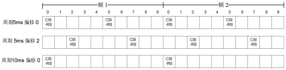
[0247] The base station sends periodic pilots to the terminal, and for the periodic pilots, the base station does not expect to restrict all subframes for sending periodic pilots to have exactly the same pilot transmission parameters. Therefore, the base station groups subframes into groups, and several simple grouping methods such as Figure 6a As shown, one is to divide subframe 0 in each frame into subframe group 1, and subframe 5 into subframe group 2; the...

example 2

[0286] Example 2: Port groups are configured with pilot parameters respectively, on the base station side.

[0287] Sub-example 1 of Example 2: Port grouping:

[0288] The base station divides the X ports to be transmitted downlink measurement pilot signals into Y port groups: port group 1, port group 2... port group Y, where Y is less than or equal to X. Each port group can contain 1 or multiple ports.

[0289] Examples of several simple port grouping methods are as follows.

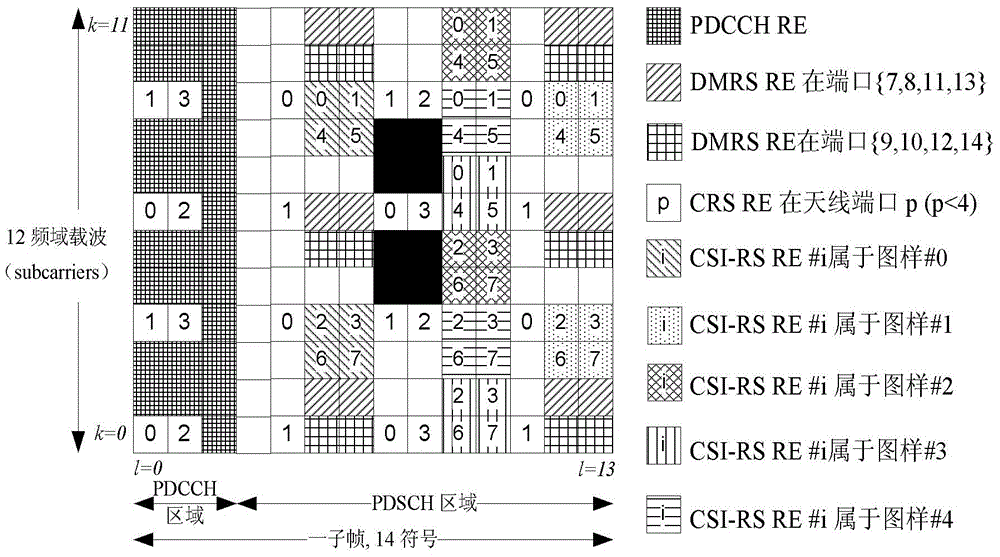
[0290] Method 1: block grouping method, each block is a group, such as Figure 7 shown.

[0291] Method 2: Row grouping method: the antenna port of each row is an antenna group such as Figure 8 shown.

[0292] Method 3: Polarization grouping method: An antenna port for each polarization direction is an antenna group, such as Figure 9 shown.

[0293] There are also some mixed methods for grouping, such as the combination of method 3 and method 1, the combination of method 3 and method 1, etc. T...


PUM


Abstract

The invention provides a downlink pilot frequency transmission method, a detection method, a device, a base station, and a terminal. The method comprises the steps that the base station enables the resources of a to-be-transmitted downlink measurement pilot signal to be divided into a plurality of resource group, wherein the resource comprises any one or random combination of a subframe, a port and a PRB pair (physical resource block pair); the base station respectively configures and/or sets the pilot frequency transmission parameters of each resource group along with the terminal; the base station transmits the downlink measurement pilot signal in each resource group according the pilot frequency transmission parameters configured for each resource group and/or set along with the terminal. The invention can provide a more flexible downlink pilot frequency transmission scheme.

Description

technical field [0001] The present invention relates to the communication field, in particular to a downlink pilot transmission method, detection method, device, base station, and terminal in the wireless communication field. Background technique [0002] In a wireless communication system, the transmitter often uses multiple antennas to obtain a higher transmission rate. Multiple antennas can improve the signal-to-noise ratio and support more spatial multiplexing layers. Compared with the open-loop MIMO (Multi-inputMulti-output, multiple input and multiple Output) technology, the MIMO technology (closed-loop MIMO precoding (Precoding)) using CSI information will have a higher capacity, and is a transmission technology widely used in the current mainstream 4G standard. The core idea of ​​closed-loop MIMO precoding technology is that the receiving end feeds back channel information to the sending end, and the sending end uses some transmit precoding techniques according to t...

Claims


Application Information

Patent Timeline
IPC IPC(8): H04L5/00H04W72/04
CPCH04L5/0023H04L5/005H04L5/0091H04W72/23H04L5/0048H04B7/0626H04W72/0446H04W88/02H04W88/08
Inventor 陈艺戬鲁照华李儒岳郁光辉
Owner ZTE CORP
Why Eureka
Try Eureka