Network cable deconcentrator

A splitter, network cable technology, applied in electrical components, coupling devices, circuits, etc., can solve problems such as pain, numbness of fingers, affecting the craftsmanship and work efficiency, and achieve low cost, simple and reasonable structure, flexible and convenient use. Effect

Inactive Publication Date: 2015-12-23
STATE GRID SHANDONG ELECTRIC POWER +1
View PDF6 Cites 2 Cited by
  • Summary
  • Abstract
  • Description
  • Claims
  • Application Information

AI Technical Summary

Problems solved by technology

[0003] The key to successful operation is whether the eight twisted-pair wires in four groups can be separated and straightened. If a large number of crystal heads need to be made during da

Method used


Image

  • Network cable deconcentrator

Examples


Embodiment 1

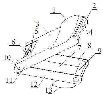
[0021] Such as figure 1 As shown, a network cable splitter includes a bottom plate 7 and a pressure plate 3, a first vertical plate 8 and a second vertical plate 12 are vertically arranged on the bottom plate 7, and the distance between the first vertical plate 8 and the second vertical plate 12 is Same width as four twisted pairs side by side.

[0022] The third vertical plate 2 and the fourth vertical plate 11 are vertically arranged on the pressing plate 3, and the spacing between the third vertical plate 2 and the fourth vertical plate 11 is greater than the spacing between the first vertical plate 8 and the second vertical plate 12; As preferably, the inside of the first riser 8 is about 0.1-0.2 mm apart from the outside of the third riser 2, and the outside of the second riser 12 is about 0.1-0.2 mm away from the inside of the fourth riser 11; based on the above requirements , In general, the distance between the third vertical board 2 and the fourth vertical board 11 i...


PUM


Abstract

The invention discloses a network cable deconcentrator, and belongs to the field of machinery. According to the network cable deconcentrator disclosed by the invention, a cable stroking post (9) is arranged between a first vertical plate (8) and a second vertical plate (12); the first vertical plate (8) and the second vertical plate (12) simultaneously play roles of a limiting baffle plate and prevent network cables from being scattered; and a cable outlet (5) is reserved at the rear end of a pressure plate (3). The lengths of the deconcentrated and stroked network cables are not limited; and the deconcentrated and stroked network cables adapt to various requirements. After the network cable deconcentrator disclosed by the invention is pressed, a gap is reserved between a deconcentrating pin (4) and the cable stroking post (9), so that the network cables can be conveniently pressed on the cable stroking post (9). The network cable deconcentrator is simple and reasonable in structure, low in cost, and flexible and convenient to use, and simultaneously has the functions of deconcentrating and stroking the network cables.

Description

technical field [0001] The invention relates to the mechanical field, in particular to a network cable splitter. Background technique [0002] The network cable is composed of four sets of twisted pairs with different colors. The production of the known crystal head is to separate and straighten the four sets of twisted pairs twisted together. , brown in order. At present, the commonly used method is: pinch the root of a group of twisted pairs, rotate the twisted wires in the opposite direction, insert a screwdriver into the gap created by the twisted wires, and then pull it out, so that a group of twisted pairs is separated. By analogy, use the same method to separate the other three sets of twisted-pair wires, then put the separated eight wires together, straighten them with your hands, and then use the part of the wire crimping pliers with a knife edge to cut the end of the network wires, and put the neat eight wires together. Insert the cable into the crystal head and ...

Claims


Application Information

Patent Timeline
IPC IPC(8): H01R31/06H01R27/00
Inventor 宋亚波何良杨军吴婷马波侯洁张艳丽母慧茹常腾史家岭
Owner STATE GRID SHANDONG ELECTRIC POWER
Why Eureka
Try Eureka