Electronic equipment

A technology for electronic equipment and external equipment, applied in branch equipment, circuits, electrical components, etc., can solve the problems of substantially reduced antenna coil inductance, reduced sensitivity of received signals, and difficulty in obtaining target characteristics, and achieve the effect of improving characteristics.

Active Publication Date: 2019-03-08
DEXERIALS CORP
View PDF5 Cites 0 Cited by
  • Summary
  • Abstract
  • Description
  • Claims
  • Application Information

AI Technical Summary

Problems solved by technology

[0003] These antennas are designed so that the maximum characteristics can be obtained at the target frequency with a single antenna, however, it is difficult to obtain the target characteristics when actually installed in electronic equipment
This is due to the interference (coupling) of the magnetic field components around the antenna with the surrounding metal, etc., and the inductance of the antenna coil is substantially reduced, resulting in a shift in the resonance frequency
In addition, the received signal sensitivity decreases due to the substantial reduction in inductance

Method used


Image

  • Electronic equipment
  • Electronic equipment
  • Electronic equipment

Examples


Embodiment Construction

[0027] Hereinafter, electronic equipment to which the present invention is applied will be described in detail with reference to the drawings. In addition, this invention is not limited to the following embodiment, Various changes are possible in the range which does not deviate from the summary of this invention. In addition, the drawings are schematic, and ratios and the like of respective dimensions may differ from actual dimensions and the like. Specific dimensions and the like should be judged in consideration of the following descriptions. In addition, there may be a part in which the mutual dimensional relationship and / or ratio differs among the drawings.

[0028] [Near Field Communication System]

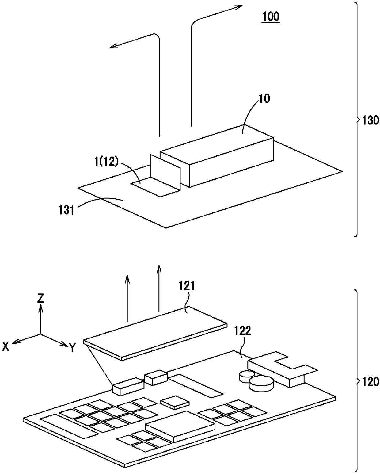
[0029] The antenna module 1 to which the present invention is applied is installed in electronic devices such as mobile phones to realize short-range wireless communication functions. Specifically, the antenna module 1 of the present invention is applied, such as figure ...


PUM


Abstract

Provided is an electronic device using an antenna module capable of being miniaturized and thinned without impairing the communication characteristics of the antenna module and that can be mounted in a reduced space. An electronic device includes an antenna module (1) having an antenna coil (12) wound in a planar shape and a magnetic sheet (13) overlapping at least a part of the antenna coil (12). And, the antenna coil (12) is bent, and the surface including the side (12a) where the current flowing in the antenna coil (12) is in the same direction from the bent portion (11a) is along the inner structure of the casing. The side surface (10a) of the object (10) is arranged adjacently, and the surface including the other side (12b) where the current flows in the opposite direction to the direction of the current flowing in one side is aligned with the magnetic sheet (13 ) are arranged in an overlapping manner, and the magnetic sheet (13) is arranged at a position farther away from the reader (120) than the other side (12b) of the antenna coil.

Description

technical field [0001] The present invention relates to an electronic device incorporating an antenna module including a loop coil and a magnetic sheet. This application claims priority based on Japanese Patent Application No. Japanese Patent Application No. 2013-176812 for which it applied in Japan on August 28, 2013, and takes in this application by referring this application. Background technique [0002] In recent wireless communication devices, antennas for telephone communication, antennas for GPS, antennas for wireless LAN / BLUETOOTH (registered trademark), and multiple RF antennas such as RFID (Radio Frequency Identification: Radio Frequency Identification) are mounted. In addition, along with the introduction of non-contact charging, a loop coil for power transmission has also begun to be installed. The power transmission method used in the non-contact charging method includes an electromagnetic induction method, a radio transmission method, a magnetic resonance met...

Claims


Application Information

Patent Timeline
Patent Type & Authority Patents(China)
IPC IPC(8): H01Q7/06H01Q1/24H01Q7/00
CPCH01Q7/06H01Q1/2216H01Q1/243H04M1/026
Inventor 折原胜久幸保雅裕
Owner DEXERIALS CORP
Why Eureka
Try Eureka