Cooling-water circulation system

A circulation system and cooling water technology, applied in the direction of water shower cooler, natural water treatment, water/sewage multi-stage treatment, etc., can solve the problems of decreased productivity, increased equipment cost, uneven product quality, etc., and achieve simple structure, The effect of water quality improvement

Inactive Publication Date: 2019-01-04
TOYOTA BOSHOKU KK
View PDF9 Cites 2 Cited by
  • Summary
  • Abstract
  • Description
  • Claims
  • Application Information

AI Technical Summary

Problems solved by technology

Therefore, corrosion (rust) of cooling pipes directly connected to the product, and hard scale (scale) mixed with silica adhere to the inside of the pipes, resulting in insufficient cooling, resulting in uneven product quality, decreased productivity, and increased equipment costs. various obstacles

Method used


Image

  • Cooling-water circulation system
  • Cooling-water circulation system
  • Cooling-water circulation system

Examples


Embodiment

[0057] Hereinafter, the present invention will be specifically described using examples using the drawings.

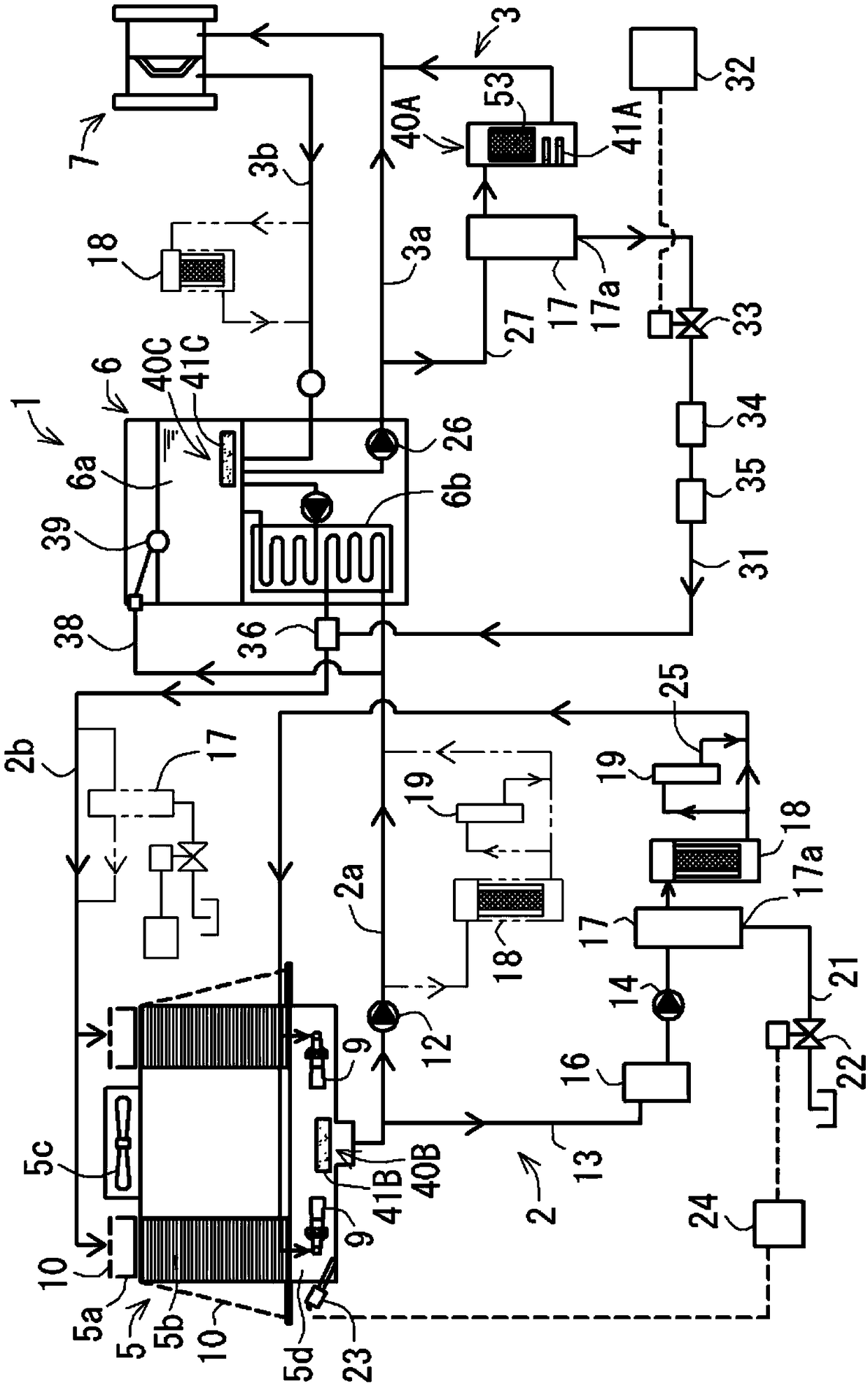
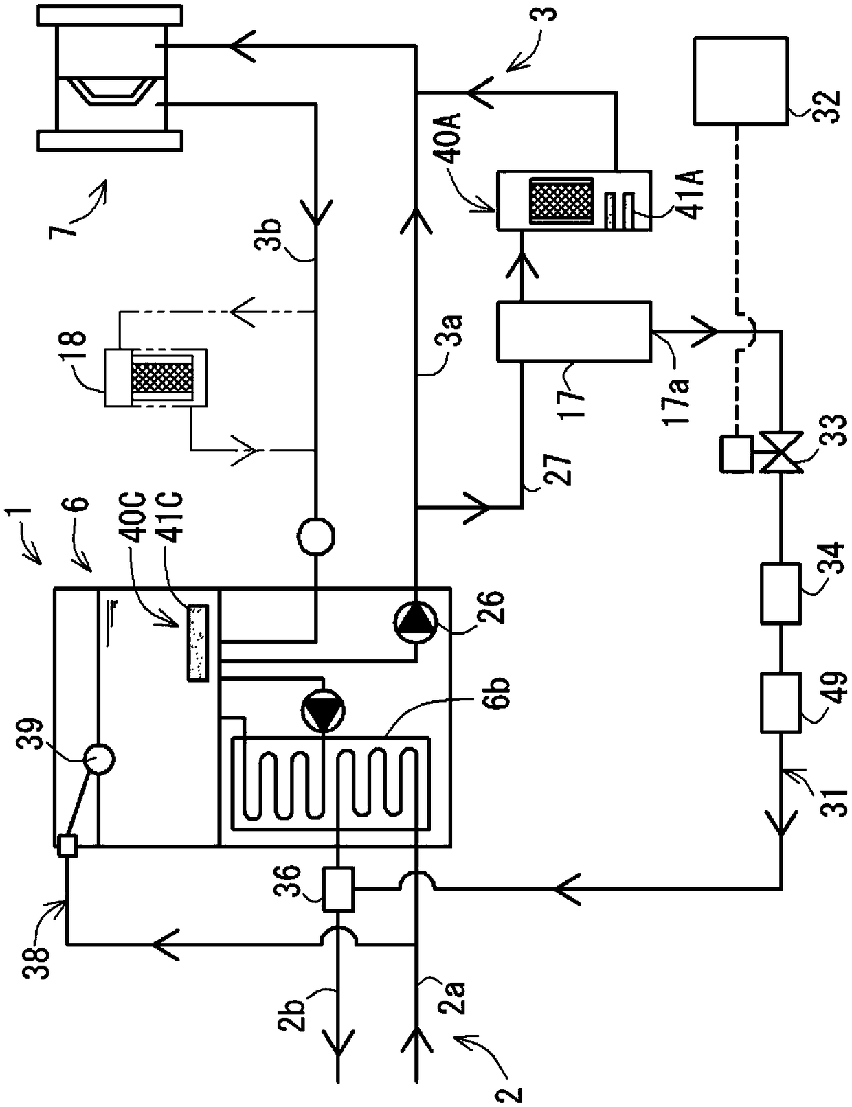
[0058] (1) The structure of the cooling water circulation system

[0059] Such as figure 1 As shown, the cooling water circulation system 1 of this embodiment includes a cooling tower side circulation path 2 (also called "primary circulation path") and a cooler side circulation path 3 (also called "secondary circulation path"). The cooling tower-side circulation path 2 circulates cooling water between the cooling tower 5 and the cooling machine 6 , and the cooling machine-side circulation path 3 circulates cooling water between the cooling machine 6 and the cooling target part 7 . In addition, examples of the cooling target portion 7 include injection molding devices, press processing devices, welding devices, heating devices, trimming devices, and the like.

[0060] The cooling tower 5 includes a water sprinkling tank 5a, a filling material 5b, a blower 5c, and a w...


PUM


Abstract

This cooling-water circulation system 1 is provided with: a cooling tower side circulation path 2 for circulating cooling water between a cooling tower 5 and a chiller 6; and a chiller side circulation path 3 for circulating cooling water between the chiller 6 and a to-be-cooled part 7. The cooling tower side circulation path 2 and the chiller side circulation path 3 are connected to each other bya first connection pipe 31 for introducing, into the cooling tower side circulation path, the cooling water circulating through the chiller side circulation path.

Description

technical field [0001] The present invention relates to a cooling water circulation system, in more detail, to a cooling water circulation system comprising a cooling tower side circulation path and a chiller side circulation path. Background technique [0002] As a conventional cooling water circulation system, a cooling water circulation system including a cooling tower side circulation path (also called "primary circulation path") and a chiller side circulation path (also called "secondary circulation path") is generally known, The cooling tower-side circulation path circulates cooling water between the cooling tower and the cooler, and the cooler-side circulation path circulates cooling water between the cooler and a cooling target (for example, refer to Patent Document 1). [0003] In the above-mentioned conventional cooling water circulation system, the circulation path on the cooling tower side and the circulation path on the chiller side are independent, and the cool...

Claims


Application Information

Patent Timeline
Patent Type & Authority Applications(China)
IPC IPC(8): F28G13/00F28F17/00
CPCF28C2001/006F28F19/01C02F2103/023C02F9/00C02F1/48C02F1/68C02F1/74C02F1/004C02F2303/08C02F2303/22F28C3/04F28F2265/20B05B7/30F28F13/08F28F27/003F28G13/00F28F17/00
Inventor 永田正辅
Owner TOYOTA BOSHOKU KK
Why Eureka
Try Eureka