A universal transmission mechanism and an omnidirectional treadmill driven by the universal transmission mechanism

A universal transmission and treadmill technology, applied in the field of machinery, can solve problems such as inconvenience in use, troublesome maintenance, and reduce the scope of application of the treadmill, and achieve the effects of a simple directional linkage mechanism, a simple basic structure, and an increase in the scope of application.

Active Publication Date: 2018-08-24
江西伊启实业有限公司
View PDF6 Cites 0 Cited by
  • Summary
  • Abstract
  • Description
  • Claims
  • Application Information

AI Technical Summary

Problems solved by technology

[0002] At present, ordinary treadmills can only complete unidirectional transmission. Such treadmills are difficult to apply to game activities, thus reducing the scope of application of treadmills. However, some existing omnidirectional treadmills can complete omnidirectional The way of movement can be divided into two types, one is to use two mutually perpendicular transmission shafts, the vertical transmission shaft is used to control the direction of the speed, and the horizontal transmission shaft is used to control the magnitude of the speed, for such a structure, The mechanism used to link the horizontal transmission shaft is very complicated, and it is prone to various failures during use, and it is also very troublesome to maintain. The other is a divergent structure, which diverges from the center of the disc to the surroundings. , this structure requires the user to change the position of the standing point to achieve movement in different directions, so it is very inconvenient to use. At the same time, the size of the treadmill is fixed, and it cannot be arbitrary according to the needs of the user and the surrounding environment. Change the size of the treadmill

Method used


Image

  • A universal transmission mechanism and an omnidirectional treadmill driven by the universal transmission mechanism
  • A universal transmission mechanism and an omnidirectional treadmill driven by the universal transmission mechanism
  • A universal transmission mechanism and an omnidirectional treadmill driven by the universal transmission mechanism

Examples


Embodiment Construction

[0021] The present invention will be described in detail below in conjunction with the accompanying drawings.

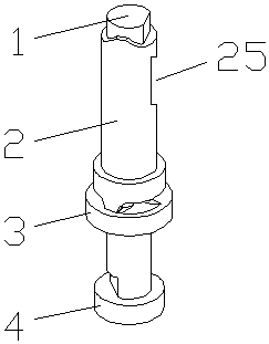
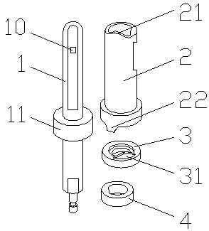
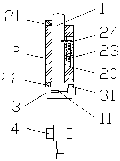
[0022] As shown in the figure, a universal transmission mechanism includes a support shaft 1, wherein a power receiving mechanism for receiving external power is provided outside the support shaft 1, and a power receiving mechanism for controlling the power transmission direction is provided outside the support shaft 1. The direction mechanism, the power receiving mechanism is connected with the direction mechanism, by controlling the rotation of the direction mechanism, the contact position between the direction mechanism and the power receiving mechanism is changed, and finally the speed direction is changed.

[0023] The power receiving mechanism includes a power input mechanism and a power output mechanism, the power input mechanism and the power output mechanism are both linked with the support shaft 1, the power output mechanism is connected with the direction m...


PUM


Abstract

The invention discloses a universal transmission mechanism and an all-directional running machine driven by the universal transmission mechanism and belongs to the field of transmission mechanisms. The universal transmission mechanism comprises a supporting frame, and a plurality of mounting holes formed in the supporting frame, wherein a plurality of supporting units are arranged on the supporting frame; each supporting unit is at least composed of three supporting bodies; the supporting bodies penetrate into the mounting holes; each two supporting bodies are connected by a speed linkage mechanism; each supporting body is connected with a direction mechanism for controlling a power transmission direction in a matching manner; the direction mechanisms are connected through a direction linkage mechanism. The universal transmission mechanism provided by the invention has a simple structure and is flexible and convenient to assemble, and the size of the whole device can be randomly adjusted according to the size of the environment; the universal transmission mechanism has very strong practicability and can be used for simply and conveniently controlling a transmission speed.

Description

technical field [0001] The invention relates to a mechanical field, in particular to a universal transmission mechanism and an omnidirectional treadmill with the transmission of the universal transmission mechanism. Background technique [0002] At present, ordinary treadmills can only complete unidirectional transmission. Such treadmills are difficult to apply to game activities, thus reducing the scope of application of treadmills. However, some existing omnidirectional treadmills can complete omnidirectional There are two ways of moving. One is to use two mutually perpendicular transmission shafts. The vertical transmission shaft is used to control the direction of the speed, while the horizontal transmission shaft is used to control the speed. For such a structure, The mechanism used to link the horizontal transmission shaft is very complicated, and it is prone to various failures during use, and it is also very troublesome to maintain. The other is a divergent structure...

Claims


Application Information

Patent Timeline
Patent Type & Authority Patents(China)
IPC IPC(8): A63B22/02
CPCA63B22/02
Inventor 成润泽
Owner 江西伊启实业有限公司
Why Eureka
Try Eureka