Automatic cleaning device for underwater measuring head of sensor
A technology for automatic cleaning and cleaning devices, applied in cleaning methods and utensils, chemical instruments and methods, cleaning methods using tools, etc., can solve the problems of reduced sensitivity of the probe and affecting the detection performance of the sensor, and achieve low manufacturing costs. Simple, good cleaning effect
- Summary
- Abstract
- Description
- Claims
- Application Information
AI Technical Summary
Problems solved by technology
Method used
Image
Examples
Embodiment 1
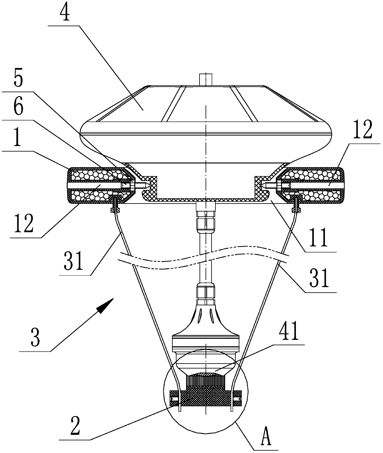
[0027] Such as figure 1 - Figure 4 As shown, an automatic cleaning device for a sensor underwater probe provided by the present invention includes a floating plate 1 floating on the water surface, a cleaning device 2 located under the water surface, and a cleaning device 2 connected between the floating plate 1 and the cleaning device 2. The connecting piece 3, the middle part of the floating plate 1 is provided with an accommodating hole 11 for accommodating the sensor 4, the lower end of the sensor 4 is placed under the water surface after passing through the accommodating hole 11, and the floating plate 1 passes through The two rotating connection points symmetrically protrudingly arranged in the accommodation hole 11 are connected with the outer circumference of the bottom of the sensor 4 under pressure, so that the floating plate 1 can not only rotate around the sensor 4 with the central axis of the sensor 4 as the center, but also rotate around the sensor 4 with a certa...
Embodiment 2
[0032] Such as Figure 5 As shown, the difference between Embodiment 2 and Embodiment 1 is that the automatic cleaning device for the sensor underwater probe also includes a limit device 7 arranged on the sensor 4 for limiting the swing range of the floating plate 1 . Of course, the limiting device 7 can also be arranged on the floating plate 1 . The limiting device 7 can effectively limit the swinging amplitude of the floating plate 1 to prevent the cleaning device 2 from falling out.
Embodiment 3
[0034] Such as Figure 6 As shown, the difference between embodiment 3 and embodiment 1 is that: the upper end surface of the floating plate 1 is provided with a vertical plate 8 perpendicular to the floating plate 1, and the vertical plate 8 is parallel to the rotating shaft of the floating plate 1. When the wind blows, the vertical plate 8 can also drive the floating plate 1 to rotate, so as to clean the measuring head of the sensor.
PUM
 Abstract
Description
Claims
Application Information
 - R&D
- Intellectual Property
- Life Sciences
- Materials
- Tech Scout
- Unparalleled Data Quality
- Higher Quality Content
- 60% Fewer Hallucinations
Browse by: Latest US Patents, China's latest patents, Technical Efficacy Thesaurus, Application Domain, Technology Topic, Popular Technical Reports.
© 2025 PatSnap. All rights reserved.Legal|Privacy policy|Modern Slavery Act Transparency Statement|Sitemap|About US| Contact US: help@patsnap.com


