Integrated combined main shaft of mill combined machining center

A composite machining and spindle technology, used in metal processing equipment, metal processing machinery parts, manufacturing tools, etc., can solve the problems of low turning accuracy, high manufacturing cost, high maintenance cost, and inability to be used more widely, and achieve cost Low, high precision, enhanced rigidity effect

Active Publication Date: 2016-04-20
广东今科机床有限公司
View PDF5 Cites 6 Cited by
  • Summary
  • Abstract
  • Description
  • Claims
  • Application Information

AI Technical Summary

Problems solved by technology

[0004] But at present, the existing milling-turning compound machining center either has the problem of low turning precision, or adopts an extremely complicated structure abroad, and its manufacturing cost and maintenance cost are high, so it cannot be used more widely.

Method used


Image

  • Integrated combined main shaft of mill combined machining center
  • Integrated combined main shaft of mill combined machining center
  • Integrated combined main shaft of mill combined machining center

Examples


Embodiment Construction

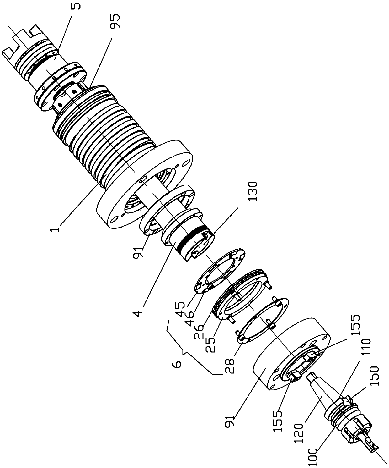
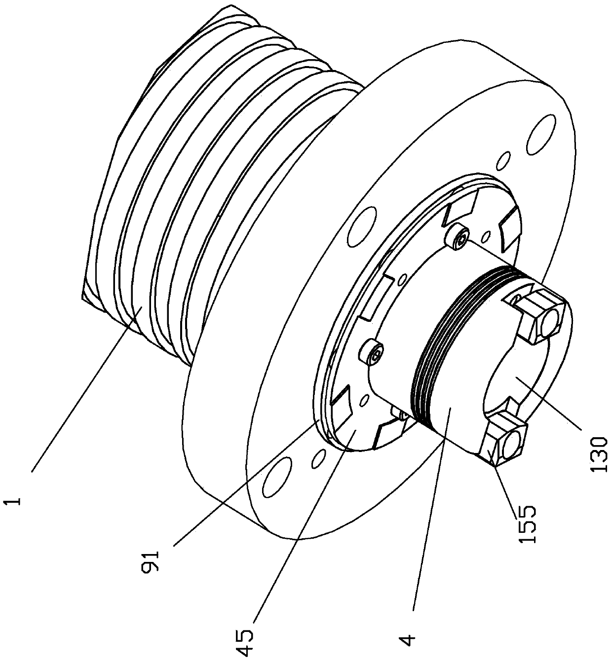
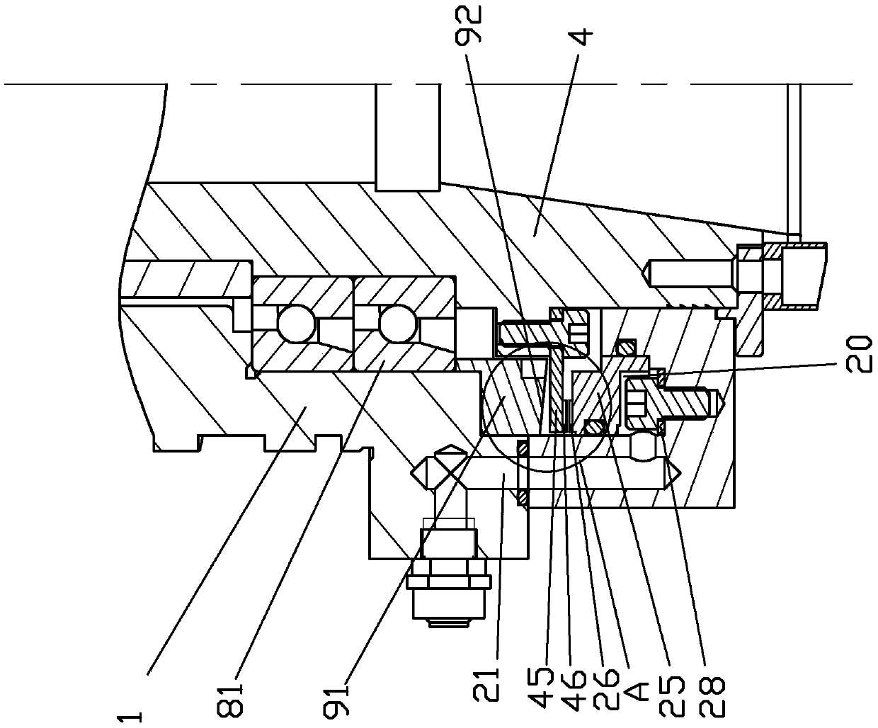
[0023] refer to Figure 1-Figure 11 , the integrated composite spindle of the milling-turning composite machining center of the present invention includes a spindle housing 1, a front end cover 2, a rear end cover 3, a spindle shaft core 4, a spindle drive mechanism 5, a locking device 6 and a broach loosening mechanism 7 .

[0024] Wherein, in view of the rear end cover 3, the main shaft drive mechanism 5 and the loose broach mechanism 7 are not the invention points of the present application, and can be replaced by common prior art, therefore, these several parts and mechanisms are not here one by one Be specific. Wherein, the main shaft driving mechanism 5 is driven to the main shaft through a coupling or a belt to provide the power source of the main shaft. In addition, the main motor has an accurate stop function, and the angular repeat positioning is 0.04 degrees.

[0025] The specific description and improvement are as follows: the main shaft housing 1 is provided wit...


PUM


Abstract

The invention discloses an integrated combined main shaft of a mill combined machining center. The integrated combined main shaft comprises a main shaft box, a front end cover, a back end cover, a main shaft core, a main shaft driving mechanism, a locking device and a broach releasing mechanism. As a first annular tooth disc and a second annular tooth disc which are fixed between a piston disc controlled through hydraulic pressure to move back and forth and an annular rotating disc fixed to the main shaft core are engaged, the repetitive positioning accuracy of the rotating angle of the main shaft are further improved; after meshing is carried out, moving is continuously carried out, the annular rotating disc is tightly pressed to a front bearing gland, and the effect of improving the rigidity of the main shaft core is achieved.

Description

technical field [0001] The invention relates to an integrated composite spindle of a milling and turning composite machining center. Background technique [0002] At present, the areas where the milling-turning integrated spindle technology is applied are mainly in Europe and Japan. They are mainly electric spindles. A high-resolution and high-repeat positioning accuracy encoder is installed in the electric spindle to solve the corner repeat positioning accuracy of 0.003 degrees for each accurate stop. Inside; a disc brake or a circumferential brake is installed in the main shaft to increase the rigidity of the tool. [0003] The milling spindle requires the spindle to have proper rotation performance, and has five degrees of freedom (XYZ movement around XY rotation) of the tool after repeated tool loading, with high repeat positioning accuracy. Turning requires high repeat positioning accuracy of the six degrees of freedom of the tool after the tool is repeatedly loaded, h...

Claims


Application Information

Patent Timeline
Patent Type & Authority Applications(China)
IPC IPC(8): B23B19/02
CPCB23Q1/70
Inventor 邝锦富
Owner 广东今科机床有限公司
Why Eureka
Try Eureka