Axial centering device of axle tube type parts

A technology for centering devices and parts, applied in positioning devices, feeding devices, metal processing machinery parts, etc., can solve the problems of difficulty in ensuring the synchronous movement of both ends of the device, poor axial centering accuracy, and complex driving sources. The structure is exquisitely designed, the impact is reduced, and the configuration is simple.

Inactive Publication Date: 2016-04-20
HEFEI PRESSURE MACHINERY
View PDF7 Cites 1 Cited by
  • Summary
  • Abstract
  • Description
  • Claims
  • Application Information

AI Technical Summary

Problems solved by technology

The existing axial centering devices for shaft and tube parts generally use hydraulic drive, that is, both ends of the shaft and tube parts are driven by oil cylinders. The disadvantage is that the driving source is complicated and needs to be equipped with a hydraulic system, which is easy to pollute and has a large force. It is easy to cause deformation of the workpiece; and because two driving sources are used at both ends, it is difficult to ensure the synchronous movement of the two ends of the device, the axial centering accuracy is poor, and the stability is poor

Method used


Image

  • Axial centering device of axle tube type parts
  • Axial centering device of axle tube type parts
  • Axial centering device of axle tube type parts

Examples


Embodiment Construction

[0023] The embodiments of the present invention are described in detail below. This embodiment is implemented on the premise of the technical solution of the present invention, and detailed implementation methods and specific operating procedures are provided, but the protection scope of the present invention is not limited to the following implementation example.

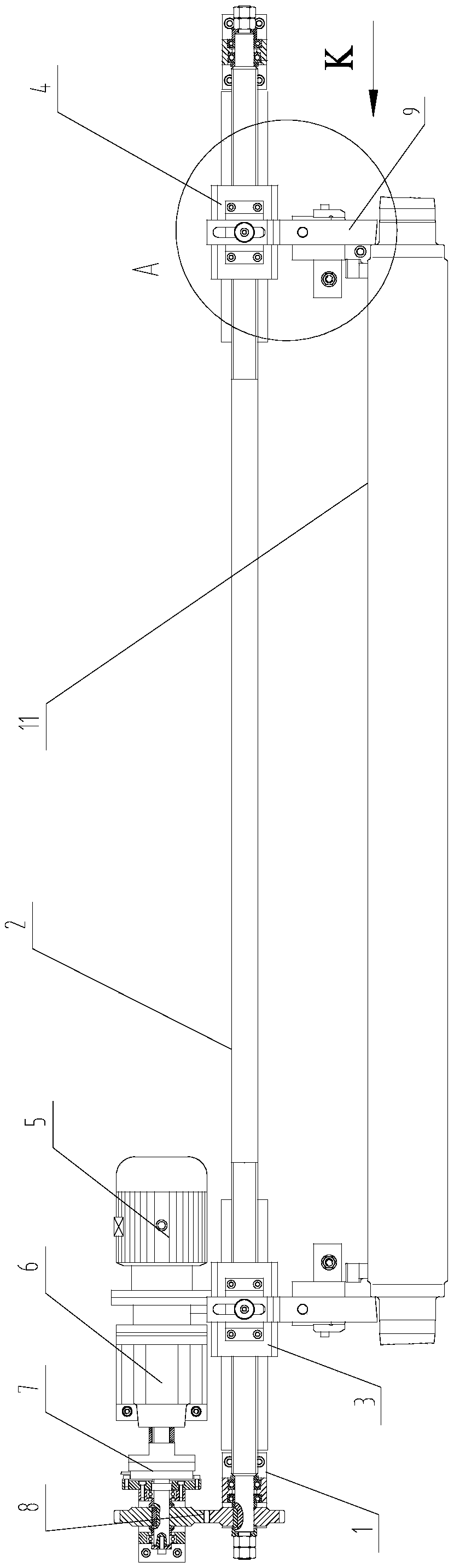
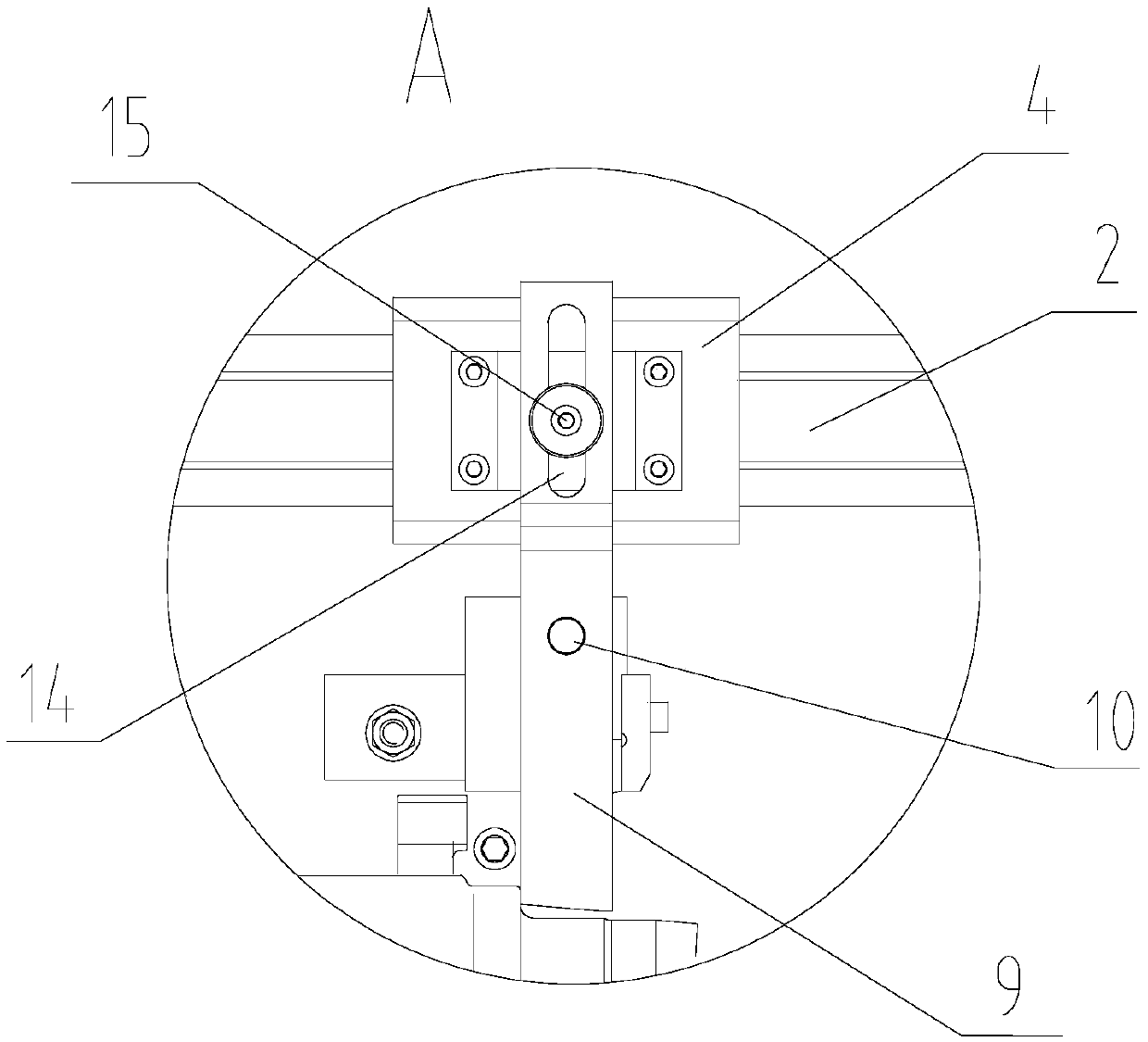
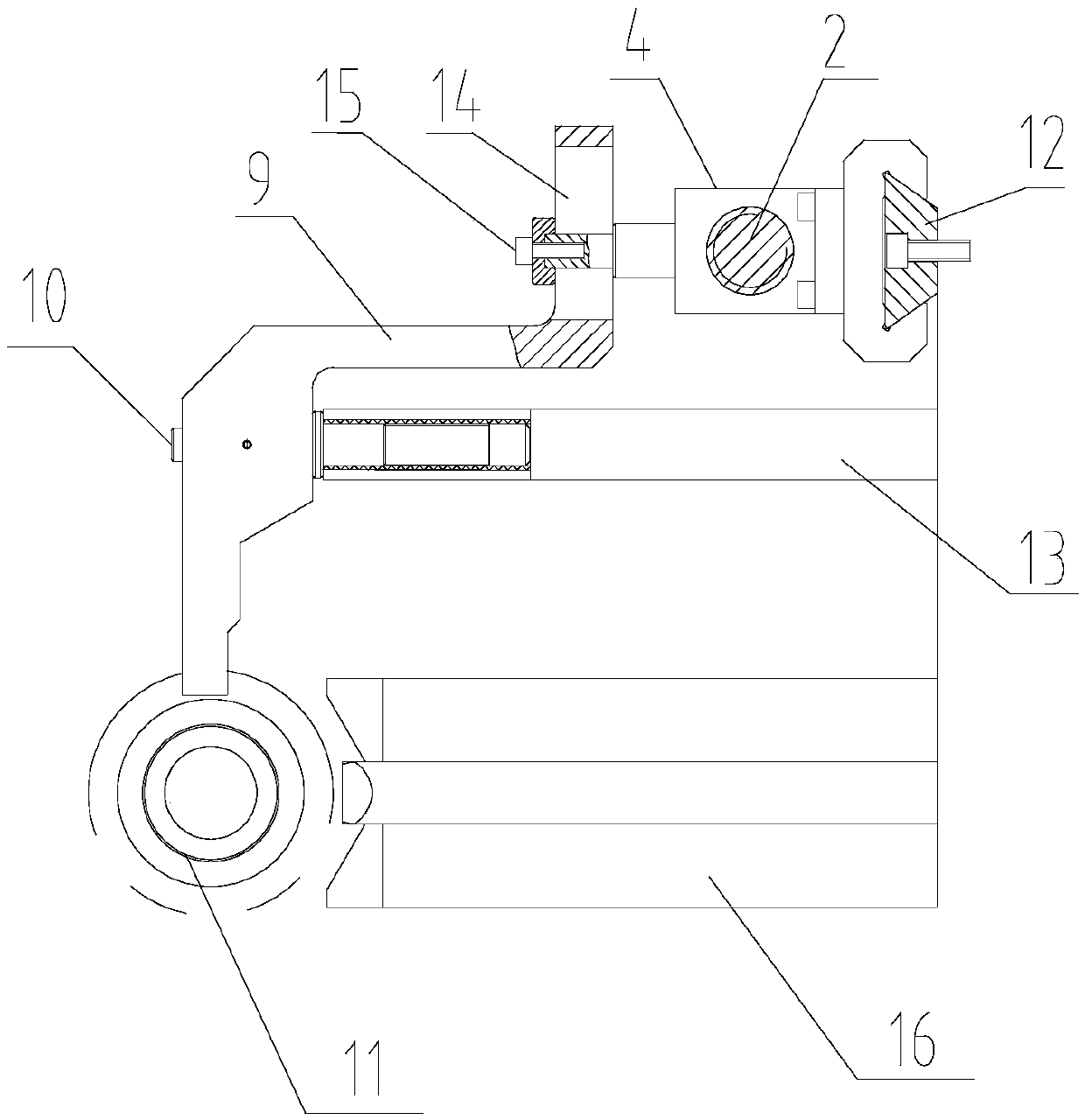
[0024] see Figure 1 to Figure 3 , this embodiment provides an axial centering device for shaft and tube parts 11, including a frame 1, on which a positive and negative screw rod 2 is rotated, and the left end of the positive and negative screw rod 2 is provided with a left external thread segment, and the positive and negative screw rod 2 is provided with a left external thread segment. The right end of the anti-screw rod 2 is provided with a right external thread segment, and the left external thread segment and the right external thread segment are opposite in direction of rotation, and the left external thread ...


PUM


Abstract

The invention discloses an axial centering device of axle tube type parts. The axial centering device comprises a rack, wherein the rack is rotatably provided with a forward-reversed screw rod; a left outer thread section is arranged at the left end of the forward-reversed screw rod and a right outer thread section is arranged at the right end of the forward-reversed screw rod; screwing directions of the left outer thread section and the right outer thread section are opposite; and the outer sides of the left outer thread section and the right outer thread section are in threaded connection with a left side block and a right slide block respectively; the forward-reversed screw rod is driven to rotate by a driving mechanism; the driving mechanism comprises a motor, a speed reducer and a clutch, which are connected in sequence; the speed reducer and the clutch are driven by the motor so that the forward-reversed screw rod is driven to rotate; the upper ends of the left slide block and the right slide block are connected with swinging arms, which extend frontwards, respectively; a vertical rotary shaft is arranged under the middle part of each swinging arm and the upper end of the rotary shaft penetrates through the middle part of the swinging arm; and the swinging arms can rotate along the rotary shafts and the front ends part of the swinging arms are used for pushing the end parts of the axle tube type parts. The axial centering device of the axle tube type parts has the advantages that the synchronism of the two swinging arms is high and the axial centering of the axle tube type parts is stable.

Description

technical field [0001] The invention relates to an axial centering device for shaft tube parts. Background technique [0002] For the machining of shaft and tube parts, it is often necessary to find the axial center of the shaft and tube parts, for example, it is necessary to drill holes at the axial center of the shaft and tube parts. The existing axial centering devices for shaft and tube parts generally use hydraulic drive, that is, both ends of the shaft and tube parts are driven by oil cylinders. The disadvantage is that the driving source is complex and needs to be equipped with a hydraulic system, which is easy to pollute and has a large force. It is easy to cause deformation of the workpiece; and because two driving sources are used at both ends, it is difficult to ensure the synchronous movement of the two ends of the device, and the axial centering accuracy is poor and the stability is poor. Contents of the invention [0003] The purpose of the present invention...

Claims


Application Information

Patent Timeline
Patent Type & Authority Applications(China)
IPC IPC(8): B23B47/20B23B49/00B23Q3/18
CPCB23B49/00B23B2215/72B23Q3/183B23Q5/40
Inventor 许文赵晓辉
Owner HEFEI PRESSURE MACHINERY
Why Eureka
Try Eureka