Snap-in floating oil seal assembling tool and implementing method thereof

A floating oil seal and buckle-type technology, which is applied in the field of assembly tools for floating oil seals, can solve the problems of difficult tool assembly and disassembly, complex structure, uneven force, etc., and achieve the effects of convenient tool removal and installation, stable structure, and convenient use

Inactive Publication Date: 2016-04-20
SHAREATE TOOLS
View PDF8 Cites 4 Cited by
  • Summary
  • Abstract
  • Description
  • Claims
  • Application Information

AI Technical Summary

Problems solved by technology

[0002] At present, there have always been two ways to assemble the floating oil seal. Small manufacturers will use PC pipes to cut axial grooves, and one end is to avoid metal inner rings and process grooves in contact with the O-ring surface as installation tools. There are problems in tool loading and unloading during...

Method used


Image

  • Snap-in floating oil seal assembling tool and implementing method thereof
  • Snap-in floating oil seal assembling tool and implementing method thereof
  • Snap-in floating oil seal assembling tool and implementing method thereof

Examples


Embodiment Construction

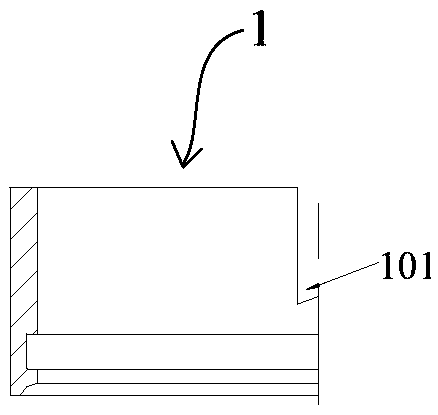
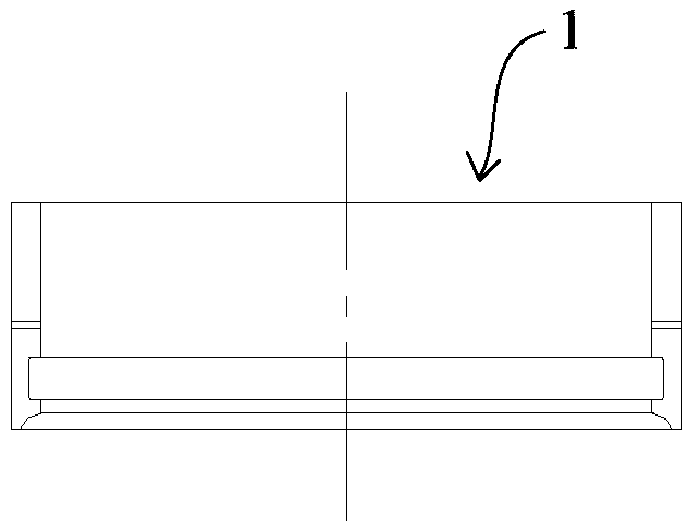
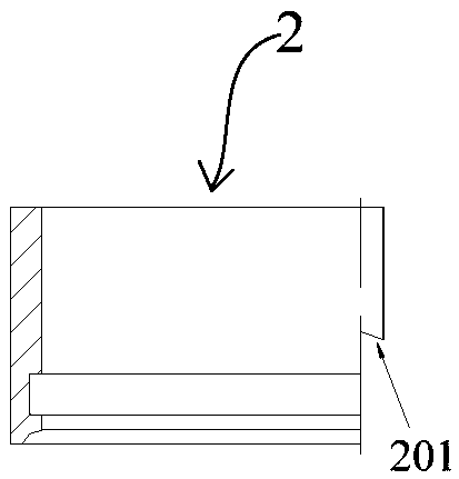
[0019] Such as Figure 1-6 As shown, the buckle-type floating oil seal assembly tool includes a left press sleeve 1, a right press sleeve 2, and a press cover 3. There is an N-type buckle-type male structure 101, and correspondingly, an N-type buckle-type female structure 201 is provided on the mating surface of the right pressure sleeve 2, and the left pressure sleeve 1 and the right pressure sleeve 2 are paired and combined to form a Complete ring structure, the upper ends of the left compression sleeve 1 and the right compression sleeve 2 are placed in the compression cover 3, and the two are combined into a whole through the compression cover 3, and the lower ends of the left compression sleeve 1 and the right compression sleeve 2 are provided for The contact portion attached to the O-ring is set as a rounded structure 4 .

[0020] Wherein, the N-type buckle-type male structure 101 includes two straight line segments parallel to the axis and an inclined segment connecting...


PUM


Abstract

The invention discloses a snap-in floating oil seal assembling tool and an implementing method thereof. The snap-in floating oil seal assembling tool comprises a left pressing sleeve, a right pressing sleeve and a pressing cover, wherein each of the left pressing sleeve and the right pressing sleeve is of a semicircular ring structure. An N-shaped snap-in male structure is arranged on a matched face of the left pressing sleeve, an N-shaped snap-in female structure matched with the N-shaped snap-in male structure is arranged on a matched face of the right pressing sleeve, and the left pressing sleeve and the right pressing sleeve are combined in a matched manner to form a complete circular ring structure. The upper ends of the left pressing sleeve and the right pressing sleeve are disposed in the pressing cover, the left pressing sleeve and the right pressing sleeve are combined into a whole through the pressing cover, and a contact portion for fitting an O ring is arranged at the lower ends of the left pressing sleeve and the right pressing sleeve. The snap-in floating oil seal assembling tool has the advantages that the matched portions of the left pressing sleeve and the right pressing sleeve are designed as N-shaped snap-in structures, the N-shaped structure match enables the left pressing sleeve and the right pressing sleeve to form a complete circular ring and limit radial movement of the left pressing sleeve and the right pressing sleeve as well as downward axial movement amount of the right pressing sleeve, and the pressing cover limits axial movement of the left pressing sleeve and the right pressing sleeve; the snap-in floating oil seal assembling tool is extremely convenient to take out and mount and is applicable to assembly of different types of floating oil seals and mounting of similar products.

Description

technical field [0001] The invention relates to an assembly tool for a floating oil seal, in particular to a buckle-type floating oil seal assembly tool and a method thereof. Background technique [0002] At present, there have always been two ways to assemble the floating oil seal. Small manufacturers will use PC pipes to cut grooves axially, and one end is to avoid the metal inner ring and the groove that is in contact with the O-ring surface as an installation tool. difficulties etc. Large manufacturers use the method of connecting the two semicircles with pins, and the contact parts between the tool and the assembly are basically the same. The tool with this structure has the problem of uneven force when it is taken out and pressed down, and its structure is too complicated. Contents of the invention [0003] The purpose of the present invention is to overcome the deficiencies of the prior art, and provide a buckle-type floating oil seal assembly tool and its method. ...

Claims


Application Information

Patent Timeline
IPC IPC(8): B25B27/02
CPCB25B27/0028B25B27/02
Inventor 谭小兰左克飞
Owner SHAREATE TOOLS
Why Eureka
Try Eureka