Arrangement of a gear on an output shaft of a transmission

a transmission and gear gear technology, applied in the direction of gearing elements, toothed gearings, gearings, etc., can solve the problems of cost efficiency and ease of mounting of spring rings, and achieve the effect of preventing unwanted rattle noises

Active Publication Date: 2010-02-11
ZF FRIEDRICHSHAFEN AG
View PDF8 Cites 4 Cited by
  • Summary
  • Abstract
  • Description
  • Claims
  • Application Information

AI Technical Summary

Benefits of technology

[0007]It is the purpose of this presented invention to improve the previously discussed con

Problems solved by technology

Such a spring ring is mounted

Method used


Image

  • Arrangement of a gear on an output shaft of a transmission
  • Arrangement of a gear on an output shaft of a transmission
  • Arrangement of a gear on an output shaft of a transmission

Examples


Embodiment Construction

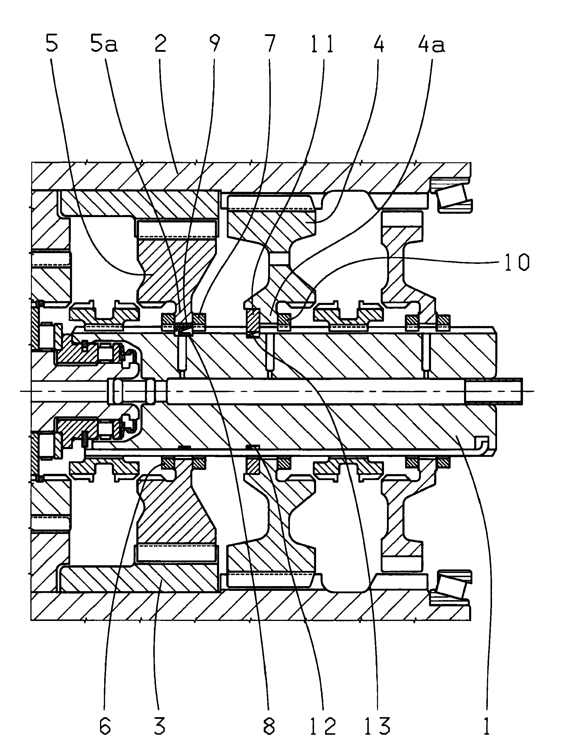
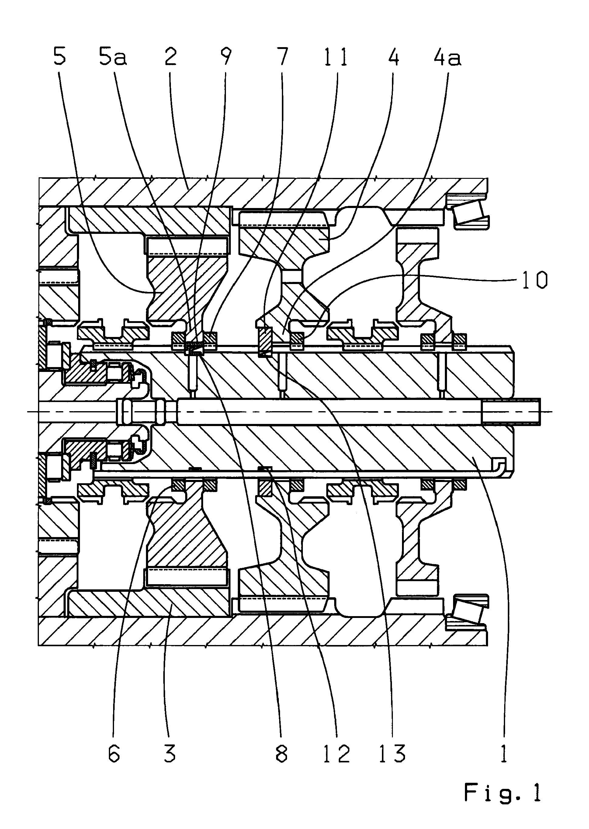
[0017]FIG. 1 shows the segment of a transmission comprising a main shaft 1 and two lay shafts 2, 3, only being partially shown. Two gear wheels (toothed wheel) 4, 5 are positioned on the main shaft 1 and serve as the transmission's 1st and 2nd gears. In each case, the gear wheels 4, 5 mesh with the lay shaft 2, 3. The gear wheels 4, 5 are designed as idle gears, also called sum gears, and are movable in the radial direction, in relation to the main shaft 1, for reasons of the load equalization, meaning that radial play exists between the sum wheels 4, 5 and the main shaft 1. The gear wheel 5 comprises a hub area 5a which is maintained in position by a thrust washer 6, 7 on each side. An elastic element, configured as a spring ring 8, is mounted between the hub area 5a and the main shaft 1. In addition, a slide ring 9 is mounted between the spring ring 8 and the hub area 5a. Because of the combination of the spring ring 8 and the slide ring 9, radial movement between the gear wheel 5...


PUM


Abstract

A configuration of a gear wheel (4, 5) on a main shaft (1) of a transmission, having at least two lay shafts (2, 3). The wheel (4, 5) is designed as a sum wheel or gear wheel, meshes with both of the lay shafts (2, 3), and is movable in the radial direction between lay shafts (2, 3). An elastic element (8, 13) is positioned, between the gear wheel (4, 5) and the main shaft (1), and/or between the gear wheel and the lay shaft to reduce radially movement of the gear wheel (4, 5).

Description

[0001]This application is a National Stage completion of PCT / EP2008 / 053542 filed Mar. 26, 2008, which claims priority from German patent application serial no. 10 2007 015 998.8 filed April 3, 2007.FIELD OF THE INVENTION[0002]The invention concerns an arrangement of a gear on an output shaft of a transmission, comprising at least two lay shafts.BACKGROUND OF THE INVENTION[0003]It is known that in transmissions comprising a main shaft and at least two lay shafts, load equalization of the gear wheels, which are positioned on the main shaft, also called sum wheels, takes place in the radial direction. The sum wheels, which mesh with the gearing of the lay shaft, are positioned so that they can move radially and opposite to the main shaft, and are steered radially by the gearing of the lay shaft and centered, respectively. Axial guidance of the sum wheels, which are designed as gear wheels in a transmission, takes place through laterally mounted thrust washers.[0004]Such a configuration...

Claims


Application Information

Patent Timeline
IPC IPC(8): F16H57/02F16H57/021
CPCF16H3/095Y10T74/19633Y10T74/19647F16H57/021
Inventor BADER, JOSEFRENNER, STEFAN
Owner ZF FRIEDRICHSHAFEN AG
Why Eureka
Try Eureka