
Lamellar roof

a technology of lamellar roof and spherical roof, which is applied in the direction of roofs, superstructure subunits, mechanical devices, etc., can solve the problems of relatively high manufacturing accuracy requirements and achieve the effect of reducing tolerance variations and simplifying the operating mechanism

Inactive Publication Date: 2005-05-10
CTS FAHRZEUG DACHSYST
View PDF8 Cites 0 Cited by
  • Summary
  • Abstract
  • Description
  • Claims
  • Application Information

AI Technical Summary

Benefits of technology

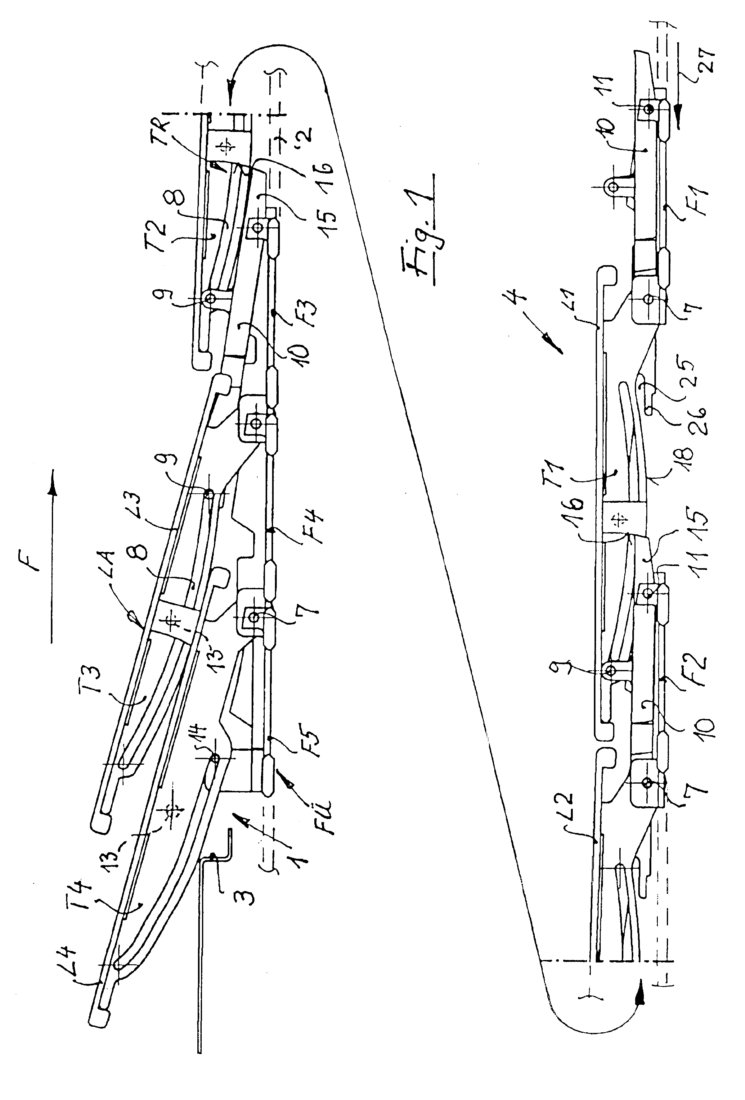
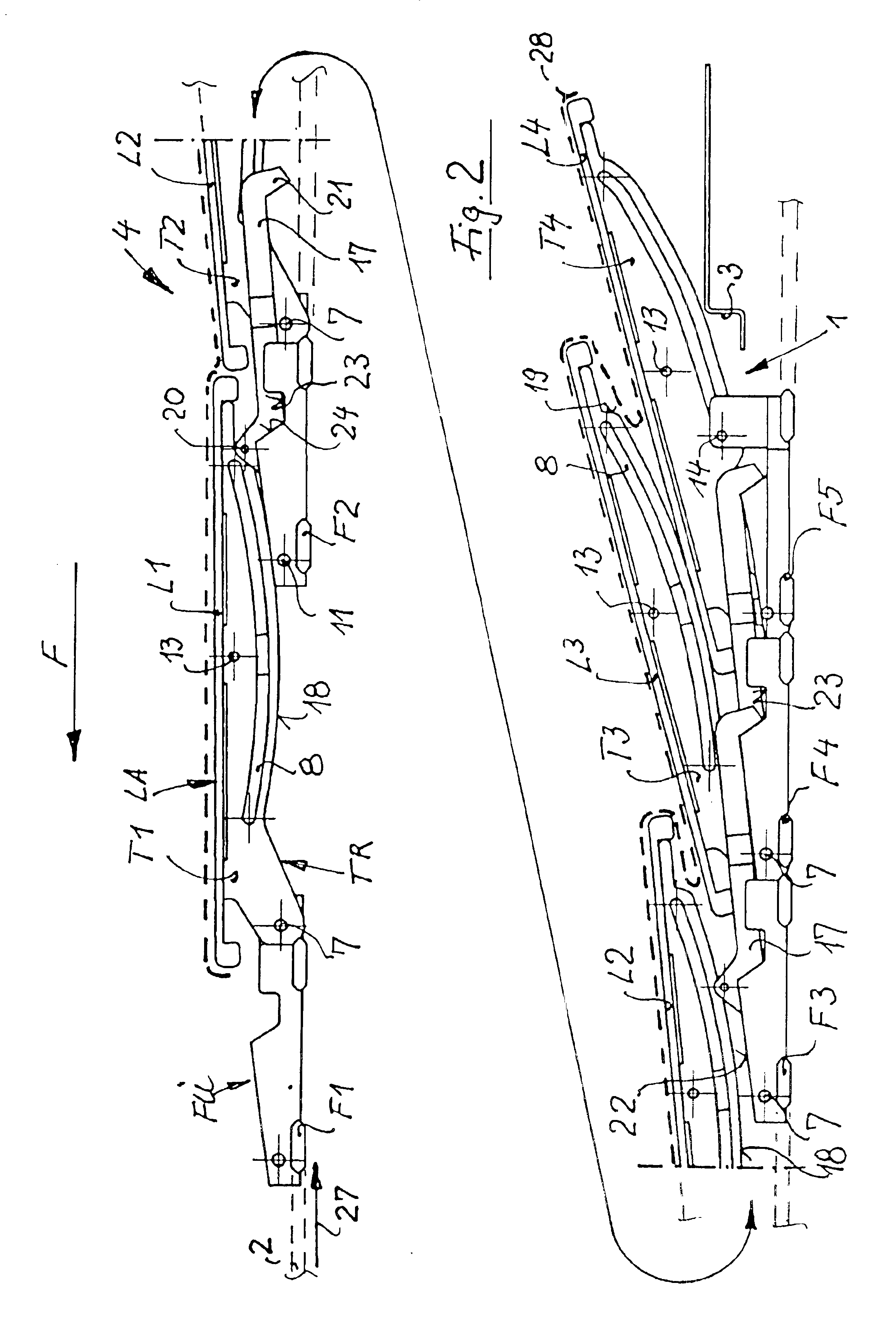
[0006]In a lamellar roof for a motor vehicle a support structure for the roof lamella section is provided in which the guide and operating mechanism is simplified and tolerance variations are reduced and which provides for firm support of the roof lamella sections also when the roof is open to avoid rattling noises. This is achieved in that the lamella sections are supported by lamella carriers and each lamella carrier is supported on two adjacent guide carriages, and a control rocker is provided on each carriage so as to be movable out of a basic closed position to a roof opening position, in which it raises the rear edges of said lamella sections to tilt the lamella section upwardly, the guide carriage of said front lamella section carrier and the control rocker projecting, in opening direction, beyond said connection and being supported, in the projecting area, on the lamella carrier.
[0007]With the arrangement according to the invention, lever lengths can be used which require only relatively small operating forces to actuate and move the roof sections and which also limit the need for small tolerances. In addition, the overlap of the control rocker and the lamella, which in the travel direction of the vehicle is in front of the control rocker, can be advantageously used to support this lamella in the opening direction of the lamellar roof and also in the opposite direction with respect to the rear guide carriage. This also permits a locking of the rear lamella depending on the tilt angle.
[0008]A slide engagement of adjacent guide carriages can be combined in the arrangement according to the invention with little efforts with an interlocking of the guide carriages, which abut each other when the lamellar roof is in an open position. The locking levers provided herefor may be connected to the respective guide carriage preferably co-axially with the control rocker which is relatively simple and also not tolerance-sensitive.
[0009]Furthermore, the locking lever may advantageously have a double function, that is, as described above, it may be used for the interlocking of the carriages when they abut one another and also as stop for the, in travel direction, front lamella or, respectively, its carriage. This stop can be used additionally for providing a longitudinally firm engagement of adjacent lamella carriers by way of the respective control rockers when appropriately designed. As a result, the respective engagement surfaces are subjected only to lower loads. They may also be so designed that in the locking positions, the respective abutment surfaces are firmly engaged with each other which is important for securing the roof structure to provide rigidity and to avoid rattling noises.
[0011]Because the locking lever, the control rocker and the lamella carrier, which are associated with a particular guide carriage and supported thereon, are also oriented in the slide direction of the lamellar roof and in an overlapping relationship and because, in the open position of the lamellar roof and with the guide carriages being disposed adjacent one another, not only the upward tilted roof lamellas with the associated lamella carriers overlap in the slide direction of the roof but also the locking levers and the control rockers of subsequent guide carriages, the control rockers can be utilized for supporting the lamella carriers against the guide carriage which is next adjacent in the opening direction of the lamellar roof. It is in this respect particularly advantageous to utilize the support pin of the control rocker, which is supported on the rearwardly adjacent guide carriage and which is guided in the guide grooves of a lamella carrier, as coupling element for the control rocker which is supported on the preceding guide carriage and which is locked when this guide carriage engages the support pin. With such a support arrangement, control rockers of subsequent guide carriages form support triangles, which stiffen the arrangement of outwardly tilted lamellas. The respective engagement of the control rockers, which are coupled together by way of the support pins, increases the rigidity of the structure.

Problems solved by technology

However, the guide structure has to accommodate relatively large forces and must be manufactured with small tolerances so that such a solution has relatively high manufacturing accuracy requirements.

Method used


Image

  • Lamellar roof
  • Lamellar roof
  • Lamellar roof

Examples


Embodiment Construction

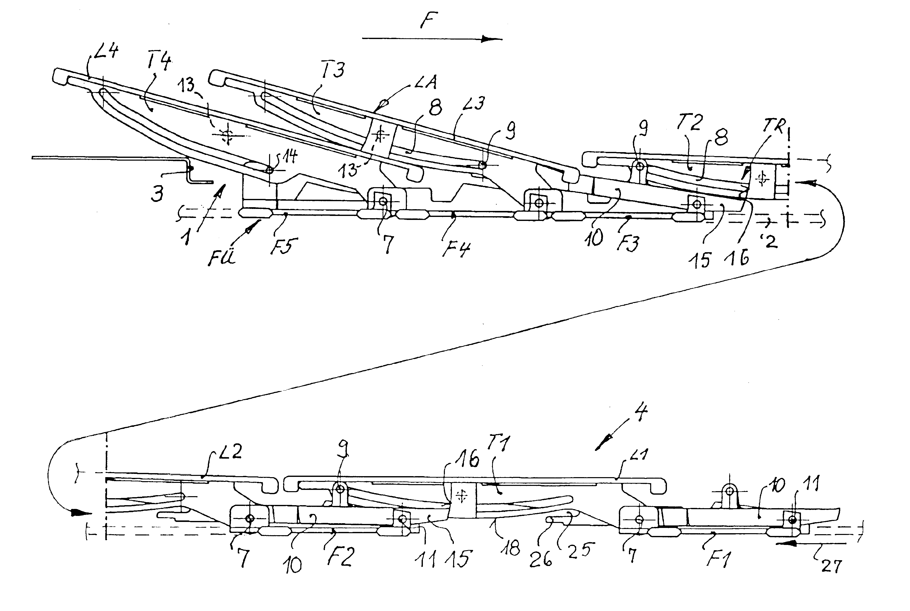
[0020]FIGS. 1 and 2 shows a lamellar vehicle roof according to the invention, partially opened that is moved toward the rear end of the roof opening 1 of the vehicle and supported in guide tracks 2 extending along the roof opening 1 up to the rear delimitation 3 of the roof opening 1. When the lamellar roof 4 is closed, the roof opening 1 is covered by the lamellas LA, specifically lamellas L1 to L4, which then form a closed sealed flat structure. In the partially open position as shown in FIGS. 1 and 2, the lamellas L2 to L4 are inclined upwardly and as shown for the lamellas L3 and L4 in an overlapping relationship. In this position, the lamellas have been moved in a direction opposite to the direction of the arrow F, which indicates the forward travel direction of the vehicle.

[0021]The lamellas L1 to L4 are supported on the vehicle body by way of the guide carriages FÜ, that is carriages F1 to F5. Each of the lamellas is supported on two guide carriages FÜ, for example, the lamel...


PUM


Abstract

In a lamellar roof for a motor vehicle a support structure for the roof lamella section is provided in which the guide and operating mechanism is simplified and tolerance variations are reduced and which provides for firm support of the roof lamella sections also when the roof is open to avoid rattling noises. This is achieved in that the lamella sections are supported by lamella carriers and each lamella carrier is supported on two adjacent guide carriages, and a control rocker is provided on each carriage so as to be movable out of a basic closed position to a roof opening position, in which it raises the rear edges of said lamella sections to tilt the lamella section upwardly, the guide carriage of said front lamella section carrier and the control rocker projecting, in opening direction, beyond said connection and being supported, in the projecting area, on the lamella carrier.

Description

[0001]This is a Continuation-in-Part application of international application PCT / EP02 / 04013 filed Apr. 10, 2002 and claiming the priority of German application 101 19 701.2 filed Apr. 20, 2001.BACKGROUND OF THE INVENTION[0002]The present invention relates to a lamellar roof for a roof opening of a motor vehicle including at least two lamella sections, which are mounted in the roof opening and which are supported on tracks so as to be movable between a closed position in which they close the roof opening and an open position in which they are tilted upwardly in the rear and moved backwardly into a sandwiched position essentially out of the roof opening.[0003]Such a lamellar roof is known for example from DE 199 24 654 C1. In the lamellar roof structure disclosed therein, the upward tilting of the rear ends of the lamellas is achieved by a positive coupling of the lamella carrier of the first lamella with a control rocker of the next adjacent carrier of the second lamella. The contro...

Claims


Application Information

Patent Timeline
Patent Type & Authority Patents(United States)
IPC IPC(8): B60J7/047B60J7/04
CPCB60J7/047
Inventor SALZ, WOLFRAM
Owner CTS FAHRZEUG DACHSYST
Learn More