
Winding mechanism for sunscreen

A technology of winding mechanism and sunshade screen, which is applied in the direction of vehicle subunit functions, windows, windshields, etc., and can solve the problems of the sunshade screen being rolled onto the winding tube due to the deployment force of the sunshade screen

Active Publication Date: 2018-06-19
INALFA ROOF SYST GROUP
View PDF10 Cites 0 Cited by
  • Summary
  • Abstract
  • Description
  • Claims
  • Application Information

AI Technical Summary

Problems solved by technology

For example, the spring member may cause a higher deployment force of the sun visor or the winding mechanism may not be able to wind the sun visor onto the winding tube

Method used


Image

  • Winding mechanism for sunscreen
  • Winding mechanism for sunscreen
  • Winding mechanism for sunscreen

Examples


Embodiment Construction

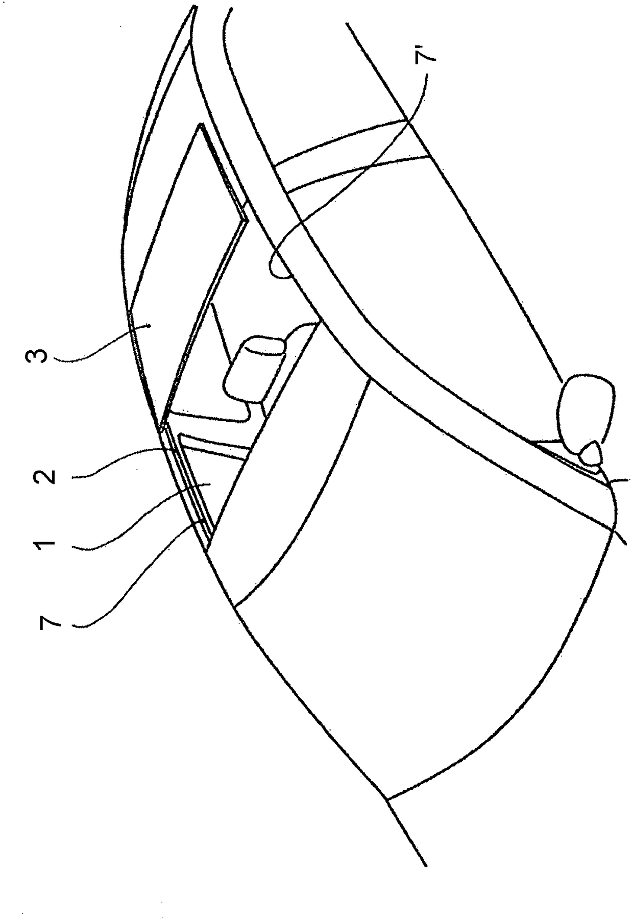
[0041] refer to figure 1 , showing a part of a vehicle with a fixed roof provided with an open roof construction. As shown, there is a roof opening 1 defined in the fixed part 2 of the open roof construction.

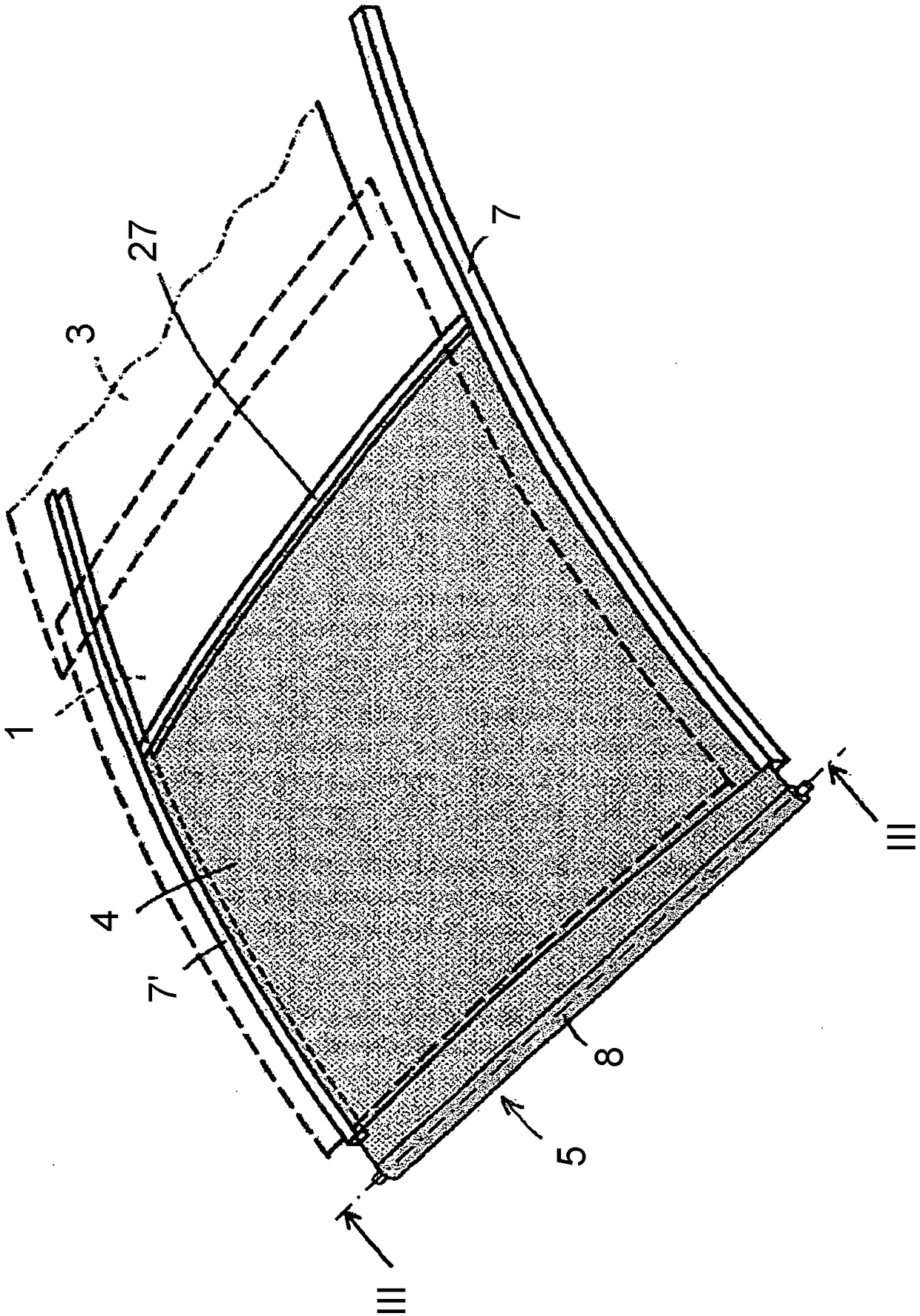
[0042] At least one movable closing member (here an at least partially transparent, rigid panel 3 ) for opening and closing said roof opening 1 is provided. figure 2 A sun visor assembly is shown, which cooperates with said roof opening 1 for covering the roof opening 1 from below in order to partially or completely prevent sunlight from entering the vehicle part. The sunshade assembly basically includes a flexible sunshade 4, a rotatable winding mechanism 5 for winding or unrolling the flexible sunshade 4, and two long shafts for cooperating with a corresponding one of the longitudinal sides of the sunshade 4. Strip-shaped guide members 7, 7'. The lateral edge of the sun visor 4 remote from the winding mechanism 5 is provided in a manner known per se with an operat...


PUM


Abstract

A winding mechanism for a sunscreen (4) and for use in an open roof construction for a vehicle comprises a winding shaft (6) which is supported at each longitudinal end to a stationary part (2) of theopen roof construction and forms a central axis for rotation. A winding tube (8) for winding and unwinding the sunscreen (4) is rotatable around the central axis. At least one spring member (10) is configured to bias the winding tube in a direction for winding the sunscreen thereon. The spring member is arranged adjacent to an inner surface of the winding tube (8) and an outer surface of the winding shaft (6). At least one sleeve (13, 13') is configured to engage the spring member (10) and inhibit the noise from the spring member. The sleeve (13, 13') comprises an inner surface and an outer surface, wherein the at least one sleeve is connected along its inner surface to the winding shaft (6) or along its outer surface to the winding tube (8).

Description

technical field [0001] The invention relates to a roll-up mechanism for a sunscreen for use in an open-roof construction of a vehicle according to the preamble of claim 1 . Background technique [0002] In prior art sunscreens with a roll-up mechanism (also known as Rollo screens), the spring member (usually a metal helical torsion spring) is covered by a sleeve which prevents the spring member from contacting the roll-up tube. It is also possible to mount the winding shaft inside the hollow shape of the helical torsion spring and wherein a sleeve is used around the shaft to prevent the spring from contacting the outer surface of the shaft, such as disclosed in EP 2 610 093 . When the sleeve is not in use, the spring member will rattle or scrape against the inner surface of the winding tube or the outer surface of the winding shaft, causing an unpleasant noise to the occupants of the vehicle. Such noises may occur when the winding mechanism is in operation and when the veh...

Claims


Application Information

Patent Timeline
IPC IPC(8): B60J7/08B60J7/00
CPCB60J7/0015B60J7/085B60J1/2033B60Y2306/09B65H2701/175
Inventor P·J·W·蒙斯特斯
Owner INALFA ROOF SYST GROUP
Learn More