
Caliper brake pad spring and brake device

a technology of brake device and brake pad, which is applied in the direction of axially engaging brakes, braking elements, brake types, etc., can solve the problems of noise generation from the movement of the brake pad, and achieve the effect of preventing rattle noise, minimizing the difference in load, and easy mounting

Active Publication Date: 2021-06-10
HYUNDAI MOBIS CO LTD
View PDF7 Cites 0 Cited by
  • Summary
  • Abstract
  • Description
  • Claims
  • Application Information

AI Technical Summary

Benefits of technology

The caliper brake pad spring described in this patent allows for better load distribution on brake pads during braking and release, while also preventing rattling noise. It is easy to install and can continue to maintain its position through the use of pressing protrusions and stoppers. The brake pad spring prevents separation from the caliper body, prevents brake pad damage, and provides better reliability by being supported by rebound support portions. The weight of the brake pad spring is also reduced due to weight-reducing hole portions.

Problems solved by technology

At this time, the movement of the brake pad may generate noise, which is problematic.

Method used


Image

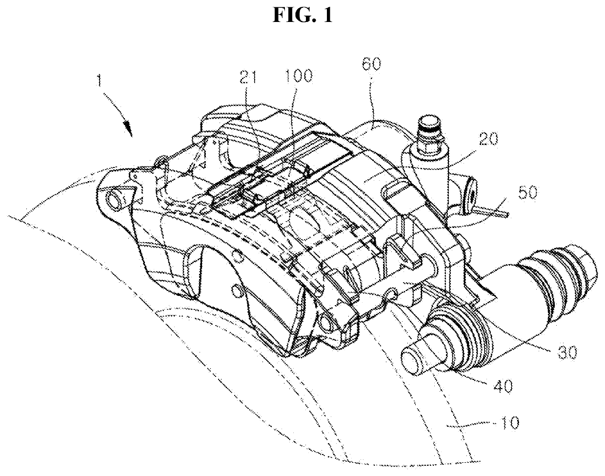
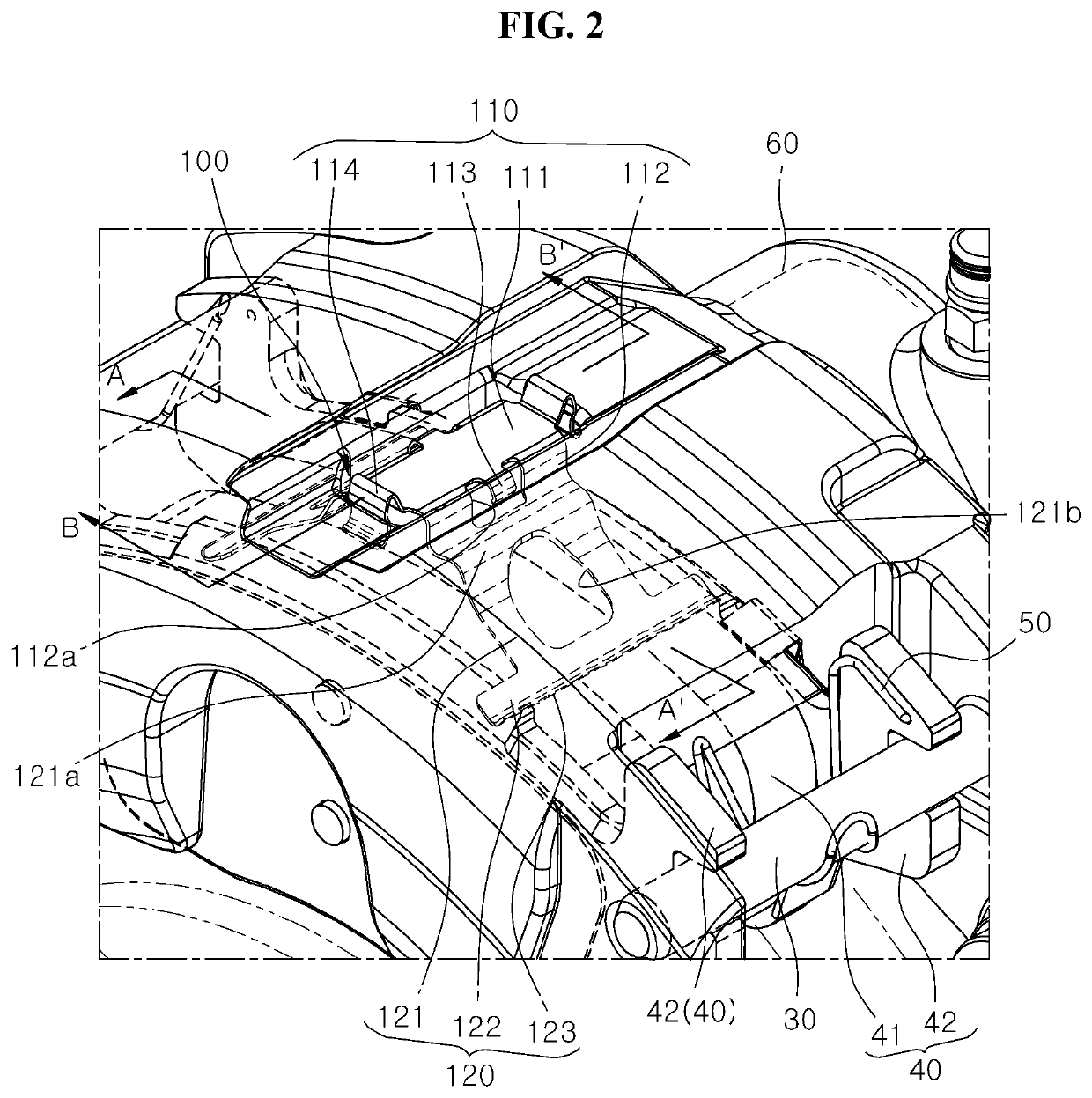
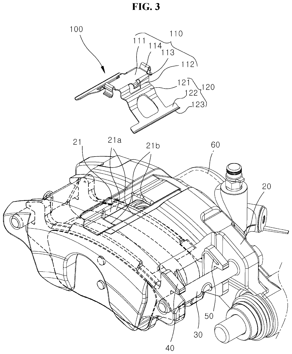
  • Caliper brake pad spring and brake device
  • Caliper brake pad spring and brake device
  • Caliper brake pad spring and brake device

Examples


Embodiment Construction

[0039]The invention is described more fully hereinafter with reference to the accompanying drawings, in which embodiments of the invention are shown. This invention may, however, be embodied in many different forms and should not be construed as limited to the embodiments set forth herein. Rather, these embodiments are provided so that this disclosure is thorough, and will fully convey the scope of the invention to those skilled in the art. In the drawings, the size and relative sizes of layers and regions may be exaggerated for clarity. Like reference numerals in the drawings denote like elements.

[0040]Hereinafter, a caliper brake pad spring according to an embodiment of the present disclosure will be described with reference to the accompanying drawings.

[0041]In the following description, the thicknesses of lines or the sizes of components illustrated in the drawings may be exaggerated for clarity and convenience of explanation. In addition, terms used herein are defined in consid...


PUM


Abstract

Provided is a caliper brake pad spring applying load to a brake pad in a set position. A spring mounting unit is mounted on a window of a caliper body. Spring pressing units extend from both sides of the spring mounting unit in one direction to apply load to a brake pad by pressing the brake pad.

Description

CROSS-REFERENCE TO RELATED APPLICATION[0001]This application claims priority from and the benefit of Korean Patent Application No. 10-2019-0161368, filed on Dec. 6, 2019, which is hereby incorporated by reference for all purposes as if set forth herein.BACKGROUNDField[0002]Exemplary embodiments of the present disclosure relate to a caliper brake pad spring, and more particularly, to a caliper brake pad spring applying load to a brake pad in a set position.Discussion of the Background[0003]In general, a brake device of a vehicle is an important device used to decelerate or stop the vehicle or maintain the vehicle in a parked position. The brake device generally uses a friction brake that performs a braking action by reducing kinetic energy of the vehicle using frictional force and discharging energy generated by the friction to the air.[0004]The brake device includes a main brake used when driving a vehicle and a parking brake used when parking the vehicle. An operating mechanism of ...

Claims


Application Information

Patent Timeline
Patent Type & Authority Applications(United States)
IPC IPC(8): F16D65/097F16D55/226F16D65/00
CPCF16D65/0979F16D2055/0016F16D65/0068F16D55/226F16D65/0977F16D55/24F16D65/0978F16D2055/0041
Inventor PARK, SANG JUN
Owner HYUNDAI MOBIS CO LTD
Learn More