
Push rod mechanism of device applicable to automatic demolding of motor coils

A technology of automatic demoulding and ejector mechanism, applied in the field of ejector mechanism, can solve the problems of high processing cost, difficult to guarantee product quality, instability, etc., and achieve the effect of high degree of automation, improved production efficiency and smooth connection

Inactive Publication Date: 2016-04-20
德清奥士玛数控设备有限公司
View PDF5 Cites 0 Cited by
  • Summary
  • Abstract
  • Description
  • Claims
  • Application Information

AI Technical Summary

Problems solved by technology

[0002] In the production process of the motor coil, it is necessary to first install the mold base for coil winding, then wrap the tape, and finally take out the mold base and coil. The existing motor coil production process is manual work, including manual tape wrapping and manual removal of the mold base. And manually take out the coil, there are problems such as high processing cost, low production efficiency and difficult to guarantee product quality
There are some devices with automatic structure at present, but the defect of this type of device is: the structural design of the connection between the upper frame and the lower frame of the demoulding device is unreasonable, so that the whole demoulding process is cumbersome, unstable and difficult to produce. Inefficiency and other disadvantages

Method used


Image

  • Push rod mechanism of device applicable to automatic demolding of motor coils
  • Push rod mechanism of device applicable to automatic demolding of motor coils
  • Push rod mechanism of device applicable to automatic demolding of motor coils

Examples


Embodiment Construction

[0017] Combine below Figure 1 to Figure 7 Specific description embodiment:

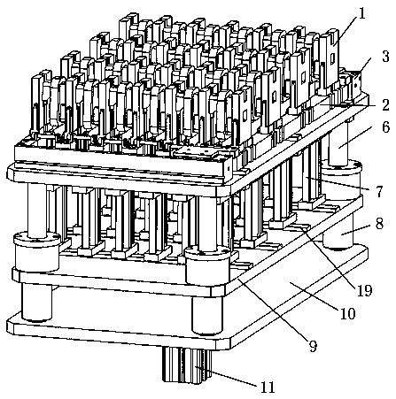
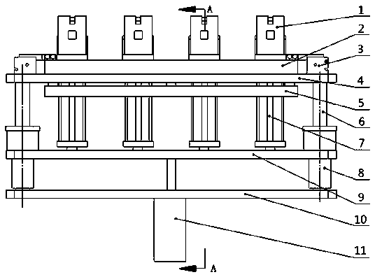
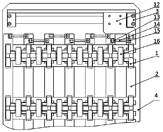
[0018] Such as Figure 1 to Figure 7 As shown, it is suitable for the automatic demoulding device of the motor coil, including the lower machine base plate 10, the upper machine base plate 4, the jacking cylinder 11, the guide post 6, the ejector rod installation plate 9, the ejector rod 7, and the mold frame installation block 2 1. The mold opening and closing cylinder 3 and the mold frame 1, the lower machine base plate 10 and the upper machine base plate 4 are fixed by the guide column 6, the jacking cylinder 11 is arranged below the lower machine base 10 plate, and the output shaft of the jacking cylinder 11 passes through the The lower base plate 10 is connected with the ejector rod mounting plate 9, and the ejector rod mounting plate 9 is pushed to move up and down. The ejector rod mounting plate 9 is slidably arranged on the guide post 6, and the guide post 6 is provided with a guide sleeve 8...


PUM


Abstract

The invention belongs to the technical field of automatic demolding tools for motor coils and particularly relates to a push rod mechanism of a device applicable to automatic demolding of the motor coils. The push rod mechanism of the device applicable to automatic demolding of the motor coils comprises an upper motor base plate, a push rod mounting plate, push rods, mold base mounting blocks and mold bases, each mold base mounting block is provided with a convex rib, and a groove is formed below each mold base, wherein each groove is matched with the corresponding convex rib of the corresponding mold base mounting block, and every two adjacent mold bases form a coil station. The push rod mechanism of device has the advantages that the structure is simple, reliability and practicality are achieved, the automation degree is high, an upper motor base and a lower motor base of the demolding device can be connected more smoothly and reasonably, production efficiency is improved, and cost is lowered.

Description

technical field [0001] The invention belongs to the technical field of automatic demoulding tools for motor coils, and in particular relates to an ejector mechanism suitable for a device for automatic demoulding of motor coils. Background technique [0002] In the production process of the motor coil, it is necessary to first install the mold frame for coil winding, then wrap the tape, and finally take out the mold frame and coil. The existing motor coil production process is manual work, including manual tape wrapping, manual removal of the mold frame And manually take out the coil, there are problems such as high processing cost, low production efficiency and difficult to guarantee product quality. There are some devices with automatic structure at present, but the defect of this type of device is: the structural design of the connection between the upper frame and the lower frame of the demoulding device is unreasonable, so that the whole demoulding process is cumbersome,...

Claims


Application Information

Patent Timeline
IPC IPC(8): B29C33/44
CPCB29C33/44
Inventor 袁京鹏王腾龙
Owner 德清奥士玛数控设备有限公司
Learn More