Can lid anti-dumping device

An anti-dumping and can lid technology, applied in the directions of transportation and packaging, conveyors, conveyor objects, etc., can solve problems such as robotic arms being unable to complete, scratching, and dumping can lids.

Active Publication Date: 2017-11-03
YIWU EASY OPEN END INDAL CORP
View PDF6 Cites 0 Cited by
  • Summary
  • Abstract
  • Description
  • Claims
  • Application Information

AI Technical Summary

Problems solved by technology

[0008] The purpose of the present invention is to solve the above-mentioned problems in the prior art, and to provide a can lid anti-dumping device, so as to solve the problem that the can lid is easily toppled over in the can collection process of the prior art, which causes the can lid to be scratched and the resistance to push the lid increases. And the manipulator cannot complete the task of grabbing the can lid, etc.

Method used


Image

  • Can lid anti-dumping device
  • Can lid anti-dumping device
  • Can lid anti-dumping device

Examples


Embodiment 1

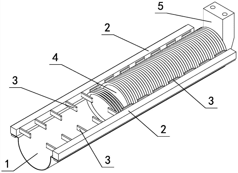
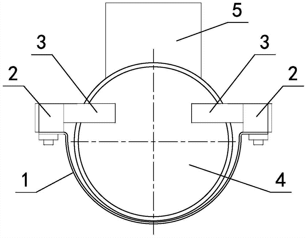
[0027] in such as figure 1 In the shown embodiment 1, a can lid anti-dumping device is arranged on the horizontal lid collection groove 1 of the can end production line, and the sheet-shaped can lids separated from each other are assembled into a cylindrical can lid 4 in the lid collection groove. The cross-section of the cover collection tank is U-shaped, and the notches on both sides of the cover collection tank are respectively provided with mounting seats 2 along the length direction of the cover collection tank. Cover strip 3, the cover strip is made of rubber or plastic material, the cover strip is horizontally arranged, one end of the cover strip is fixed with the mounting seat, the other end of the cover strip is suspended and extends into the cover collecting groove, and the cover The projected length of the suspended part of the strip on the cross section of the cover groove is 30 to 45% of the opening width of the cover groove, which is 40% in this embodiment; the d...

Embodiment 2

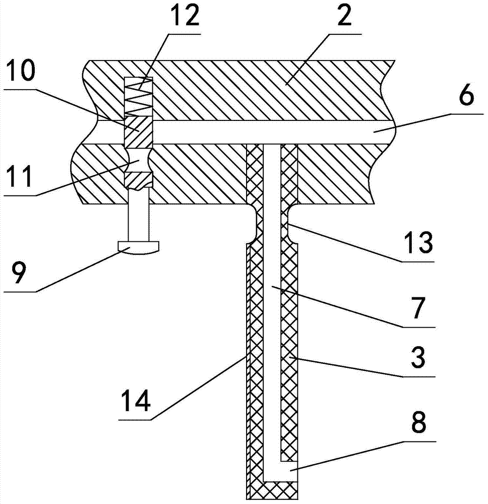
[0029] in such as Figure 5 In the shown embodiment 2, the tank cover anti-dumping device is provided with an air channel 6 connected to the air source in the length direction of the mounting seat (see image 3 , Figure 4), the cover bar is a hollow structure with an air path 7 connected to the air channel inside, and the air jet port 8 is provided at the suspended end of the cover bar, and the air jet port points to the cover groove before the cover bar is bent The upstream side of the flow direction of the can end (ie the incoming direction of the can end, see image 3 ), the side of the mounting seat facing the cover tank is provided with an airway switch 9 (see Figure 5 ), the airway switch is arranged between two adjacent cover strips and close to the upstream side cover strip in the flow direction of the cover tank cover, and the height of the airway switch is adapted to the height of the cover strip.

[0030] The airway switch of this embodiment includes a plunger ...


PUM


Abstract

The invention discloses a can cap tipping prevention device which is arranged on a horizontal cap collection groove of a can cap production line, wherein mounting seats are arranged at the cap collection groove from notches at the two sides of the cap collection groove along the length direction of the cap collection groove; elastic can blocking strips are horizontally arranged at one side, facing to the cap collection groove, of each mounting seat in a spaced manner; one end of each can blocking strip is fixed to one mounting seat correspondingly; the other ends of the can blocking strips are overhung and stretch into the cap collection groove; and the projected lengths of the overhung parts of the can blocking strips on the cross section of the cap collection groove are 30-45% of the width of an opening of the cap collection groove. With the adoption of the can cap tipping prevention device, the problems that in a can collection process in the prior art, can cap tipping happens easily, thereby resulting in that can caps are scratched, a cap pushing resisting force is increased, and a manipulator can not complete a can cap grabbing task can be solved effectively. The can cap tipping prevention device can prevent can caps from tipping effectively, the production efficiency is improved, the product quality is ensured, and the can cap tipping prevention device has very high practical values.

Description

technical field [0001] The invention relates to the technical field of pop can production equipment, in particular to a can lid anti-dumping device for preventing the can lid from falling when the sheet can lid is integrated into a cylindrical can lid. Background technique [0002] In enterprises that produce canned food, tea, food, beverages and other canned packaging products, in the production process of cans, the production process of the can lids (lids) at both ends of the cans is very complicated, from sheet material to molding to packaging. After many processes, the equipment of each process is different, and it is often necessary to switch during the production process, so each process needs to go through the process of collecting and arranging pieces of can lids (referred to as lid collection), and then transport them to the next On the equipment of a process. The process of collecting and arranging can lids (collecting lids) is to transform the can lids from the o...

Claims


Application Information

Patent Timeline
Patent Type & Authority Patents(China)
IPC IPC(8): B65G47/22
CPCB65G47/22B65G2201/0252
Inventor 骆江波杨春香姚旭飞
Owner YIWU EASY OPEN END INDAL CORP
Why Eureka
Try Eureka