Swing type flow divider valve for sluiceway

A diverter valve and swing-type technology, applied in the direction of discharge devices, etc., can solve problems such as poor sealing, and achieve the effects of improving sealing, reducing labor intensity, and reducing maintenance

Active Publication Date: 2016-04-20
鞍钢集团工程技术有限公司
View PDF5 Cites 2 Cited by
  • Summary
  • Abstract
  • Description
  • Claims
  • Application Information

AI Technical Summary

Problems solved by technology

It can effectively solve the problem of poor sealing between the gate plate and the slag ditch, improve the labor intensity of workers, reduce the amount of equipment maintenance, and reduce infrastructure investment and production and operation costs

Method used


Image

  • Swing type flow divider valve for sluiceway
  • Swing type flow divider valve for sluiceway
  • Swing type flow divider valve for sluiceway

Examples


Embodiment Construction

[0017] The invention will be described in detail below in conjunction with the accompanying drawings, but it should be pointed out that the implementation of the present invention is not limited to the following embodiments.

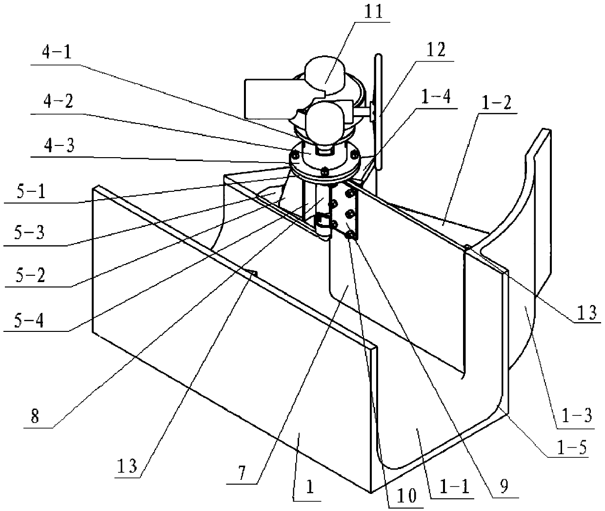
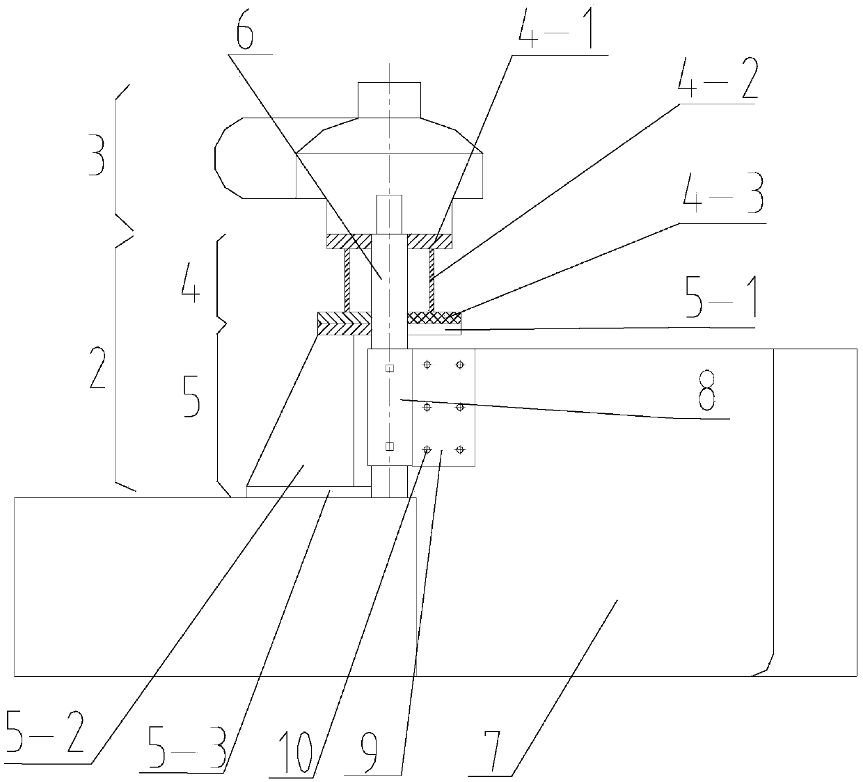
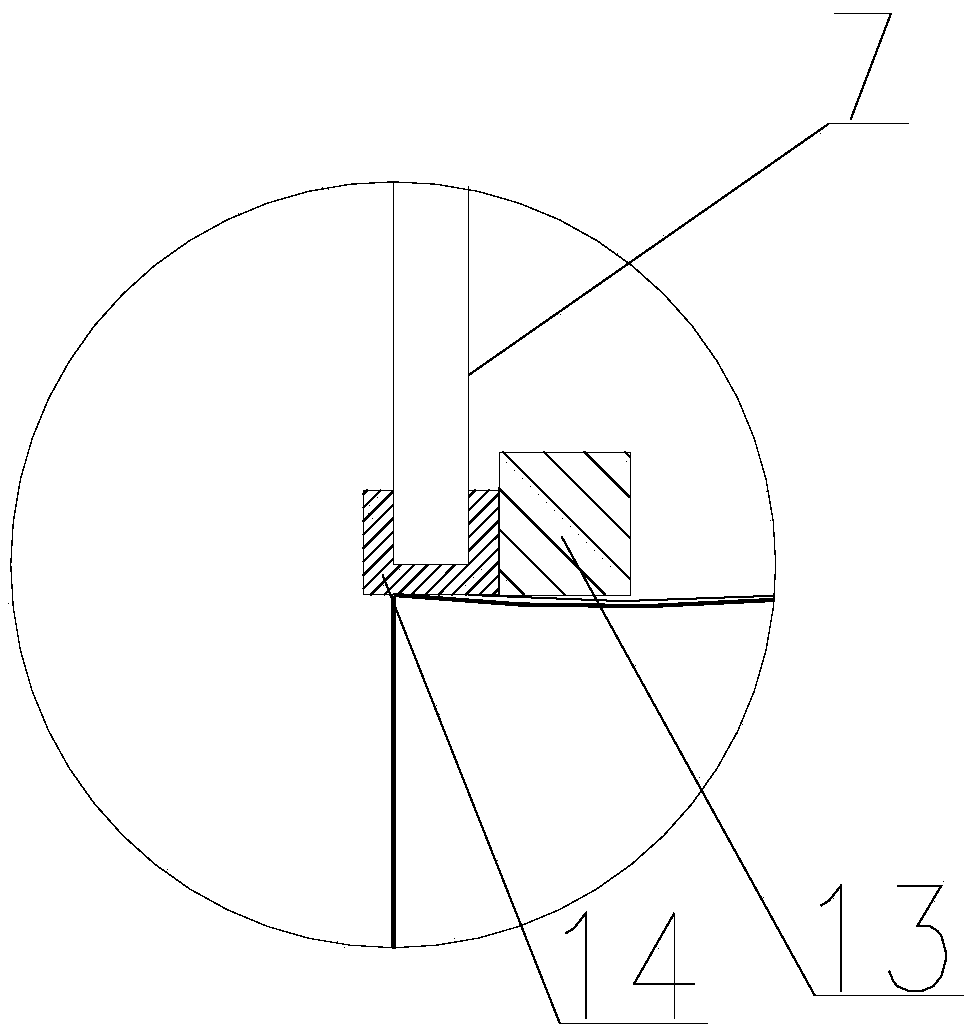
[0018] Such as Figure 1-Figure 4 As shown, a swing type diverter valve for slag flushing ditch includes a tank body 1, a valve body 2, and a transmission device 3. The tank body 1 is a three-way structure, and the main groove 1-1 of the three-way tank body is connected to the main groove body. The slag groove 16 is docked and fixed by welding, the branch groove 1-2 of the tee tank body is docked with the branch slag groove 15, and fixed by welding, the valve frame lower 5 of the valve body 2 is clamped with the main and branch grooves of the tank body 1 The angle connecting plates 1-4 are connected by bolts, and the valve plate 7 connected with the valve body main shaft 6 is arranged in the groove body 1, and the transmission device 3 is connected with ...


PUM


Abstract

The invention discloses a swing type flow divider valve for a sluiceway. The swing type flow divider valve comprises a groove body, a valve body and a transmission device. The groove body is of a three-way structure, a main groove of the three-way groove body is in butt joint with a main sluiceway body and fixed in a welding mode, a branch groove of the three-way groove body is in butt joint with a branch sluiceway body and fixed in a welding mode, the lower portion of a valve frame of the valve body is connected with a main groove and branch groove included angle connecting plate of the groove body through a bolt, a valve plate connected with a main shaft of the valve body is arranged in the groove body, the transmission device is connected with the upper portion of the valve frame of the valve body through a bolt, the upper end of the main shaft of the valve body is in transmission connection with the transmission device, the transmission device drives the main shaft of the valve body to rotate to drive the valve plate of the valve body to swing, and thus closure transformation of the flow divider valve is achieved. Compared with the prior art, the swing type flow divider valve has the advantages that due to the adoption of the swing type flow divider valve, the sealing performance between the valve plate and the sluiceway is improved, the labor intensity of workers is relieved, the equipment maintenance amount is reduced, and near half investment can be reduced in a project compared with a wedge disc used in the past.

Description

technical field [0001] The invention relates to a valve device for a slag flushing system produced by a blast furnace, in particular to a valve device which is installed at the bifurcation of a slag flushing ditch and a branch ditch, and uses a swing valve plate to divert water slag. Background technique [0002] The ram is one of the important equipment commonly used on the slag ditch of the blast furnace. At present, the ram action mode used by various production plants is the lifting type, and the ram runs along the slideway embedded in the slag ditch wall. Its disadvantages: first, there is water slag residue in the slideway, which leads to poor operation of the ram and poor sealing effect; second, the switching action between the main slag ditch and the branch slag ditch needs to be completed in two steps, which brings inconvenience to the operation; The third is that both the main slag ditch and the branch slag ditch are equipped with flashboards, and the project inves...

Claims


Application Information

Patent Timeline
Patent Type & Authority Applications(China)
IPC IPC(8): C21B3/08C21B7/14
CPCC21B3/08C21B7/14
Inventor 马海林曹帅战奇涂川徐吉林张彤宇李霞
Owner 鞍钢集团工程技术有限公司
Why Eureka
Try Eureka