Outer sleeve constrained folded steel plate energy dissipation support

An energy-dissipating support and outer casing technology, which is applied to building components, shock-proof and other directions, can solve the problems that the energy-dissipation performance of the support cannot be accurately controlled, the position of the yield point of the core board cannot be controlled, and the energy-dissipation capacity of the core board cannot be exerted. The effect of improving hysteretic energy dissipation performance, increasing hysteretic energy dissipation capacity, and optimizing energy dissipation mechanism

Active Publication Date: 2018-06-19
SOUTHEAST UNIV
View PDF7 Cites 0 Cited by
  • Summary
  • Abstract
  • Description
  • Claims
  • Application Information

AI Technical Summary

Problems solved by technology

[0004] However, there are few plastic hinges in the current buckling-constrained energy-dissipating supports, which cannot exert the energy-dissipating capacity of the entire core plate, cannot control the yield point position of the core plate, and cannot control the number of plastic hinges, which makes the energy consumption of the entire support The performance cannot be precisely controlled to achieve the desired effect

Method used


Image

  • Outer sleeve constrained folded steel plate energy dissipation support
  • Outer sleeve constrained folded steel plate energy dissipation support
  • Outer sleeve constrained folded steel plate energy dissipation support

Examples


Embodiment 1

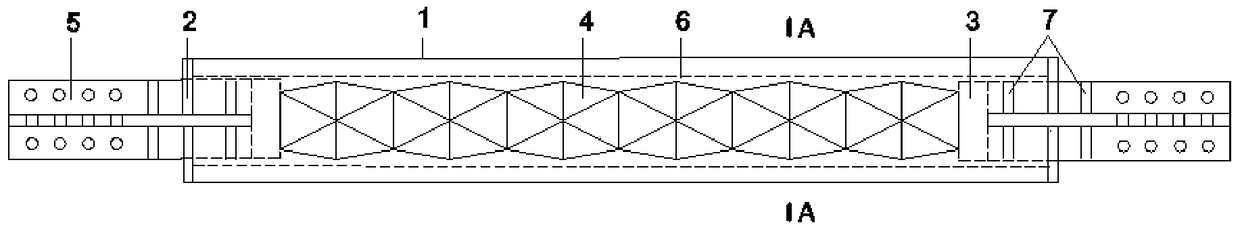
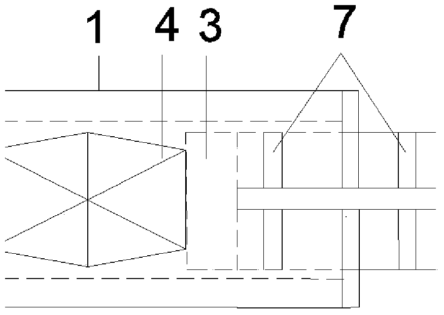
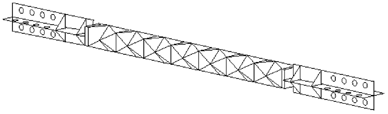
[0039] as follows figure 1 As shown in Fig. 6, the present invention is composed of seven parts: outer casing 1, outer casing sealing plate 2, end pressure plate 3, core barrel 4, cross gusset plate 5, non-adhesive material 6, and stiffener 7. The core barrel 4 is stamped from a steel plate to form different simple geometric figures, and then welded to form a cylindrical shape. As shown in FIG. 6 , in this embodiment, the geometric figures on the core barrel 4 are combinations of isosceles triangles. Figure 7 It is the crease style in this embodiment, where the dotted line is the dent, and then the two ends can be welded. Such as figure 2 As shown, the end pressure plate 3 is connected to the core barrel 4, and the end pressure plate 3 is welded to the four sides of the core barrel 4 mouth, and the size of the end pressure plate 3 is the same as that of the core barrel 4 mouth. The other side of the end pressure bearing plate 3 is welded to the cross gusset plate 5, the c...

Embodiment 2

[0041] This embodiment is the same as the rest of Embodiment 1, except that the round tube of the outer sleeve 1 is replaced by a square tube to provide constraints.

[0042] In order to express the spatial structure of the sub-unit more clearly, a space Cartesian coordinate system is established to describe the coordinates of each node, such as Figure 8 As shown, the coordinate origin O is the center of the subunit, the X-axis is the straight line where the diagonal line FH of the quadrilateral EFGH is located, the positive direction is from F to H, and the Z-axis is the straight line where the other diagonal line EG of the quadrilateral is located. E points to G as the positive direction, and the straight line passing through the point O and perpendicular to the X-axis and Z-axis is used as the Y-axis, and the positive direction is from the plane ABCD to the plane IJKL.

[0043] The size of the energy dissipation unit should meet the following conditions (θ is the dihedral ...


PUM


Abstract

The invention discloses an outer casing pipe constraint folding steel plate energy consumption support. The support comprises an outer casing pipe, a core barrel arranged in the outer casing pipe, end bearing plates arranged at barrel openings of the two sides of the core barrel and outer casing pipe seal plates arranged at the ends of the two side of the outer casing pipe; the end bearing plates are connected with cross-shaped node plates penetrating through the outer casing pipe seal plates, and the core barrel is formed by sequentially connecting multiple energy consumption units. The support reduces earthquake responses of buildings through the good post-yielding energy consumption capacity, is easy to manufacture and convenient to install and can be applied to structural earthquake resisting and effectively reduce earthquake disasters.

Description

technical field [0001] The invention belongs to the field of energy-dissipating supports of building structures, and relates to an energy-dissipating support of folded steel plates constrained by outer sleeves. Background technique [0002] Earthquake disasters are sudden and devastating, threatening the safety of human life and property. For buildings, due to the excessive seismic response of buildings, the buildings will lose their function, be seriously damaged or even collapsed. In order to reduce disasters caused by earthquakes, energy dissipation shock absorption technology is widely used in structural design. Among them, the development and application of buckling-constrained braces is a representative technology. [0003] The buckling restrained brace is mainly composed of core plate, outer casing, unbonded material and other parts. In this technology, the core plate is the main force-bearing unit, and the core plate deforms under the action of an earthquake to co...

Claims


Application Information

Patent Timeline
Patent Type & Authority Patents(China)
IPC IPC(8): E04B1/98
CPCE04B1/98
Inventor 陆金钰杨连坤谯旭东
Owner SOUTHEAST UNIV
Why Eureka
Try Eureka